
Tin-plated film and method for producing the same

a technology of tin-plated film and tin-plated ring, which is applied in the direction of semiconductor/solid-state device details, transportation and packaging, and other domestic objects, can solve the problems of short-circuiting in circuits or between terminals and noise generation, failure or obstruction of whisker generation, and increased running costs, so as to achieve high reliability, prevent discoloration, and hard to generate whiskers

Inactive Publication Date: 2006-01-26
PANASONIC CORP
View PDF6 Cites 31 Cited by
  • Summary
  • Abstract
  • Description
  • Claims
  • Application Information

AI Technical Summary

Benefits of technology

[0016] The invention was developed to solve the above-described problems and shortcomings, and it is therefore an object of the invention to provide a method for producing a tin-plated film, which is capable of preventing whiskers of tin-plated films from being generated, and preventing the surface of copper or copper alloy substrate, which is not covered with a tin-plated film, from discoloring due to oxidization by simplified operations superior in productivity.
[0019] It is thereby possible to provide a method for producing a tin-plated film, by which a tin-plated film having high reliability, which is hard to generate whiskers, can be obtained.
[0021] It is thereby possible to provide a method for producing a tin-plated film, by which a tin-plated film having high reliability and hard for whiskers to be generated can be obtained, and discoloring of the surface of a copper or copper alloy substrate not covered with a tin-plated film due to oxidization can be prevented.

Problems solved by technology

If whiskers are generated and grows in electronic components, it becomes a cause of short-circuiting in circuits or between terminals and noise generation.
In particular, since recent electronic components are inclined to downsizing, high concentration, and feeble currents, generation of whiskers is apt to arise a failure or obstruction.
However, the prior art technologies described above have the following problems and shortcomings.
However, a facility for adjusting the atmosphere is required, and at the same time the running costs are increased.
Therefore, there is a problem in that productivity is not satisfactory.
However, if quick heating is carried out at a programming rate of 5 through 100° C. per second, there arises a problem in that the surface of a substrate not covered with a tin-plated film is oxidized and is discolored.
However, there arises a problem in that the surface of a substrate to be plated, which is not covered with a tin-plated film, is discolored, and productivity is not satisfactory because the heating time is long.
In the technology described in JP-A-5-33187, there is a problem in that the processes are complicated and productivity is not satisfactory.
Also, there is another problem in that the surface of a substrate to be plated, which is not covered with a tin-plated film, is discolored.
However, whiskers cannot be effectively prevented.
However, whiskers cannot be effectively prevented as well.

Method used


Image

  • Tin-plated film and method for producing the same
  • Tin-plated film and method for producing the same
  • Tin-plated film and method for producing the same

Examples


embodiment 1

EXPERIMENTAL EXAMPLE 1

[0028] A description is given of the invention, using an electronic component lead frame used for the PPF (PrePlated Frame) system as an example.

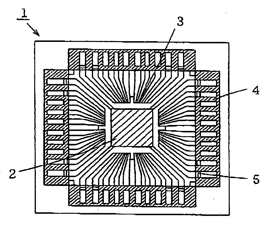
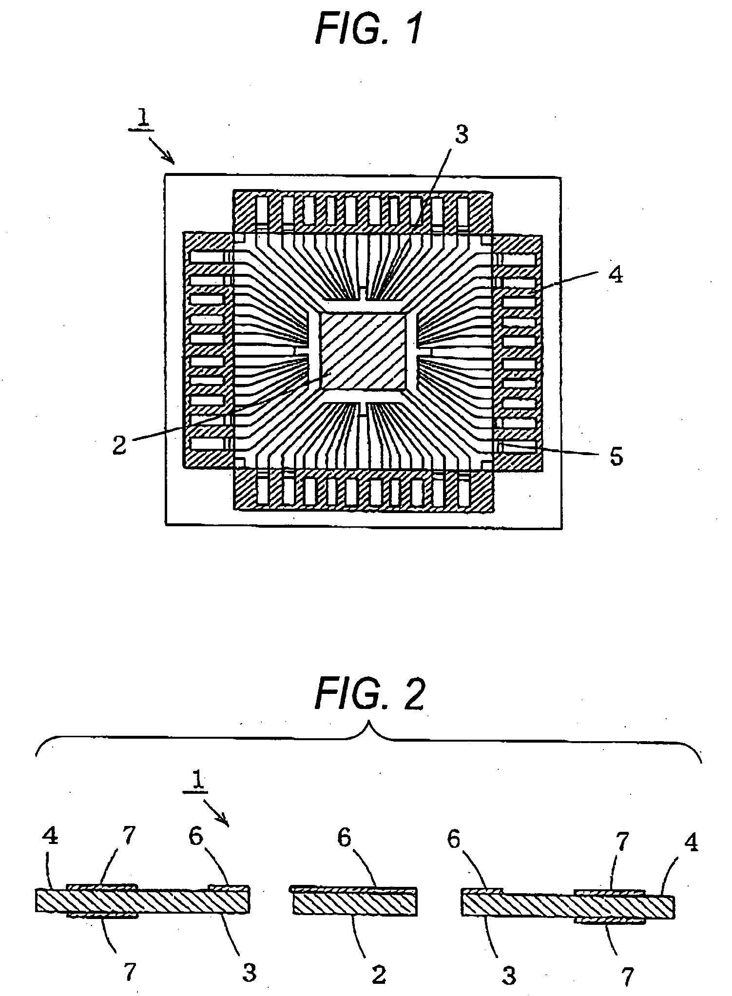
[0029]FIG. 1 is a plan view of an electronic component lead frame, and FIG. 2 is a sectional view of an electronic component lead frame.

[0030] In the drawings, reference numeral 1 denotes a lead frame whose substrate is copper or copper alloy, 2 denotes a chip-mounted portion of the lead frame 1, 3 denotes an inner lead portion radially formed at the outer side of the chip-mounted portion 2, 4 denotes an outer lead portion extending at the outer side of the inner lead portion 3, 5 denotes a tie bar portion, 6 denotes a silver or silver alloy plated film formed on the upper surface of the chip mounted portion 2 and on the upper surface of the inside end part of the inner lead portion, and 7 denotes a tin-plated film formed on the upper surface and the lower surface of the outer lead portion 4.

[0031] Here, low tin / ph...

experimental example 2

[0044] A test piece of Experimental Example 2 was obtained as in Experimental Example 1, excepting that, as the heat treatment condition in the heat treatment step, the lead frame 1 is taken out after it is inputted, for 15 seconds, in a constant temperature oven whose temperature is constantly 210° C.

[0045] In addition, as shown in Table 1, it was confirmed that the lead frame 1 (copper or copper alloy substrate), having a thermocouple, whose temperature is 25° C. (room temperature) reached 146.0° C. in 15 seconds after it was inputted in a constant temperature oven whose temperature is constantly 210° C.

experimental example 3

[0046] A test piece of Experimental Example 3 was obtained as in Experimental Example 1, excepting that, as the heat treatment condition in the heat treatment step, the lead frame 1 is taken out after it is inputted, for 15 seconds, in a constant temperature oven whose temperature is constantly 220° C.

[0047] Also, as shown in Table 1, it was confirmed that the lead frame 1 (copper or copper alloy substrate), having a thermocouple, whose temperature is 25° C. (room temperature) reached 156.3° C. in 15 seconds after it was inputted in a constant temperature oven whose temperature is constantly 220° C.


PUM

PropertyMeasurementUnit
mean grain diameteraaaaaaaaaa

Abstract

The present invention has an object to provide a tin-plated film and a method for producing the same, capable of preventing whiskers from being generated and simultaneously preventing the surface of a substrate to be plated, which is not covered with a tin-plated film, from discoloring due to oxidation, by which prevention of whisker generation, suppression of whisker growth, and prevention of discoloring of a substrate to be plated are compatible with simplified operations ensuring excellent productivity. The method is provided with the steps of removing a part of a tin-plated film formed on copper or copper alloy; processing to prevent discoloring of the copper or copper alloy from which the tin-plated film is removed; and applying heat energy to the tin-plated film of the copper or copper alloy which is processed to prevent discoloring.

Description

BACKGROUND OF THE INVENTION [0001] The present invention relates to a method for producing a tin-plated film in which whiskers are hard to be generated and hard to grow, and a tin-plated film produced by using the same method. [0002] Tin plating has been generally employed as a metallic surface processing method for ornaments, electronic components and structural parts because tin plating is inexpensive in costs, and brings about excellent durability, satisfactory appearance and an excellent soldering property. [0003] However, it has been known that needle crystal consisting of single crystal of tin called “whiskers” are generated on a tin-plated surface. The whiskers generally are 1 through 2 μm diameter, and several micrometers through several millimeters long, which is easy to be generated particularly on a brightened tin-plated film to which a brightening agent is added. If whiskers are generated and grows in electronic components, it becomes a cause of short-circuiting in circu...

Claims


Application Information

Patent Timeline
Patent Type & Authority Applications(United States)
IPC IPC(8): C25D3/30
CPCC25D5/505C25F3/02H01L23/49582Y10T428/12715H01L2224/32245Y10S428/929H01L2924/15173
Inventor TANAKA, HISAHIROOGATA, SHIGEKI
Owner PANASONIC CORP
Learn More