Methods and products for producing lattices of EMR-treated islets in tissues, and uses therefor

a technology of emr-treated islets and lattices, which is applied in the field of methods and products for producing lattices of emr-treated islets in tissues, and uses therefor. it can solve the problems of bulky tissue damage, difficult to eliminate unwanted side effects, and vessel collapse and di

Inactive Publication Date: 2006-01-26
PALOMAR MEDICAL TECH
View PDF98 Cites 234 Cited by
  • Summary
  • Abstract
  • Description
  • Claims
  • Application Information

AI Technical Summary

Benefits of technology

[0011] The present invention depends, in part, upon the discovery that, when using electromagnetic radiation (EMR) to treat tissues, there are substantial advantages to producing lattices of EMR-treated islets in the tissue rather than large, continuous regions of EMR-treated tissue. The lattices are periodic patterns of islets in one, two or three dimensions in which the islets correspond to local maxima of EMR-treatment of tissue. The islets are separated from each other by non-treated tissue (or differently- or less-treated tissue). The EMR-treatment results in a lattice of EMR-treated islets which have been exposed to a particular wavelength or spectrum of EMR, and which is referred to herein as a lattice of “optical islets.” When the absorption of EMR energy results in significant temperature elevation in the EMR-treated islets, the lattice is referred to herein as a lattice of “thermal islets.” When an amount of energy is absorbed that is sufficient to significantly disrupt cellular or intercellular structures, the lattice is referred to herein as a lattice of “damage islets.” When an amount of energy (usually at a particular wavelength) sufficient to initiate a certain photochemical reaction is delivered, the lattice is referred to herein as a lattice of “photochemical islets.” By producing EMR-treated islets rather than continuous regions of EMR-treatment, more EMR energy can be delivered to an islet without producing a thermal islet or damage islet, and / or the risk of bulk tissue damage can be lowered.
[0019] In another aspect, the invention provides methods for skin rejuvenation, skin texturing, hypertrophic scar removal, skin lifting, stretch mark removal, non-skin-surface texturing (e.g. lip augmentation), and improved wound and burn healing by treating a portion of tissue of a subject with an EMR-treatment device that produces a lattice of EMR-treated damage islets in a desired treatment area and thereby activates an natural healing and / or repair process which improves the desired tissue characteristic.
[0022] In the various embodiments of the invention, the lattices of EMR-treated islets can be heated to temperatures of 35-40° C., 40-50° C., 50-100° C., 100-200° C., or greater than 200° C. In some embodiments, the papillary dermis is not heated to a temperature above 40-43° C. to prevent pain. In some embodiments, the upper layers of the tissue are cooled to reduce heating of those layers and / or produce subsurface thermal or damage islets.
[0031] Another embodiment of the invention can be an apparatus for treating skin that includes a speed sensor. In this aspect, the apparatus features a light emitting assembly for applying optical energy to the target area of the patient's skin, the light emitting assembly including a head portion movable across the target area of the patient's skin and an optical energy source for outputting optical energy from the light emitting assembly. The source is movably mounted relative to the head, and a sensor determines the speed of movement of the head portion across the target area of the patient's skin. The apparatus can include circuitry in communication with the sensor for controlling movement of the source relative to the head portion based on the speed of movement of the head portion across the target area of the patient's skin, such that islets of treatment are formed on the target area of the patient's skin. The circuitry, for instance, can control the movement of the source such that the source is moved in a direction generally opposite the direction of movement of the head portion from a first position in the head portion to a second position in the head portion at generally the same speed as the movement of the head portion, and when the source reaches the second position, it is returned to the first position. The source can, for instance, be mounted on a linear translator in the head portion. In some aspects, the sensor can be a capacitive imaging array or an optical encoder. The source can be either a coherent or a non-coherent light source.
[0032] According to another aspect of the invention, an apparatus for performing a treatment on a target area of a patient's skin can prevent the passage of light to the patient's skin if the apparatus is not in contact with the patient's skin. Such an apparatus can feature a light emitting assembly including a non-coherent light source for applying optical energy to the target area and a plurality of light directing elements at an output end of the light emitting assembly. The light directing elements can be shaped so that substantially no light will pass through the output end when the output end is not in contact with the patient's skin. Further, the light directing elements can create treatment islets in the patient's skin during use. The light directing elements can be, for example, selected from a group including an array of pyramids, cones, hemispheres, grooves, and prisms.

Problems solved by technology

All three approaches have drawbacks, the most significant of which is the difficulty in eliminating unwanted side effects.
Usually, primary absorption of optical energy by water causes bulk tissue damage.
The thermal stress to these targets causes vessels to collapse and die, and pigmented lesions to crust over followed by sloughing-off of the dead skin.
One problem with selective photothermolysis is that the wavelength selected for the radiation is generally dictated by the absorption characteristics of the chromophore and may not be optimal for other purposes.
Unfortunately, wavelengths preferentially absorbed by melanin, for example, are also wavelengths at which substantial scattering occurs.
The fact that wavelengths typically utilized for selective photothermolysis are highly scattered and / or highly absorbed limits the ability to selectively target body components and, in particular, limits the depths at which treatments can be effectively and efficiently performed.
Further, much of the energy applied to a target region is either scattered and does not reach the body component undergoing treatment, or is absorbed in overlying or surrounding tissue.
This low efficiency for such treatments means that larger and more powerful EMR sources are required in order to achieve a desired therapeutic result.
However, increasing power generally causes undesired and potentially dangerous heating of tissue.
Thus, increasing efficacy often decreases safety, and additional cost and energy must be utilized to mitigate the effects of this undesired tissue heating by surface cooling or other suitable techniques.
Heat management for the more powerful EMR source is also a problem, generally requiring expensive and bulky water circulation or other heat management mechanisms.
Photodermal treatments are further complicated because chromophore concentrations in a target (e.g., melanin in hair follicles) varies significantly from target to target and from patient to patient, making it difficult to determine optimal, or even proper, parameters for effective treatment of a given target.
High absorption by certain types of skin, for example dark skinned individuals or people with very tanned skin, often makes certain treatments difficult, or even impossible, to safely perform.
One drawback, which severely limited popularity of this treatment in the recent years, is a prolonged post-operative period requiring continuous care.
However, clinical efficacy of the non-ablative procedure is often unsatisfactory.
However, one possibility is that damage (or lack thereof) to the epidermis may be an important factor determining both safety and efficacy outcomes.
Obviously, destruction of the protective outer epidermal barrier (in particular, the stratum corneum) in the course of ablative skin resurfacing increases chances of wound contamination and potential complications.

Method used


Image

  • Methods and products for producing lattices of EMR-treated islets in tissues, and uses therefor
  • Methods and products for producing lattices of EMR-treated islets in tissues, and uses therefor
  • Methods and products for producing lattices of EMR-treated islets in tissues, and uses therefor

Examples


example 1

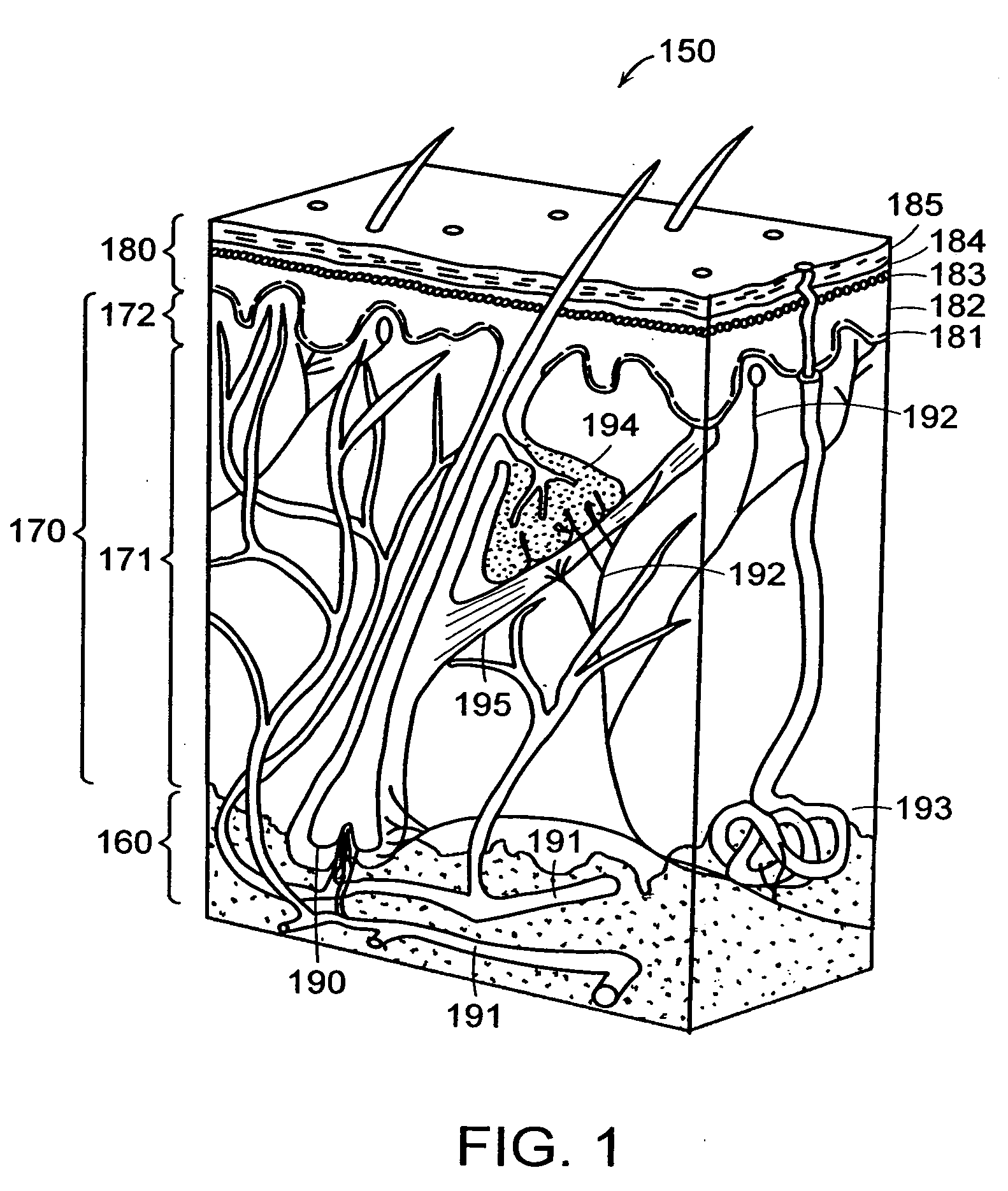
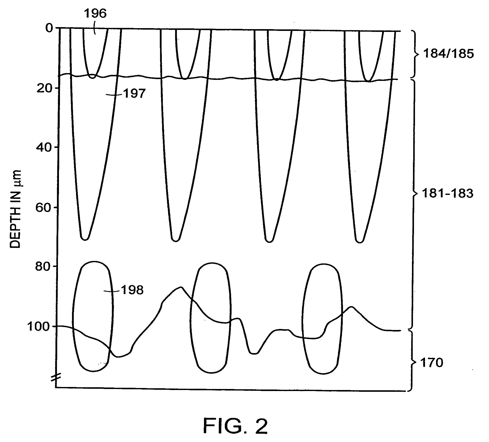
Computational and Theoretical Models of Islets and Islet Formation

[0290] The optical, thermal and damage islets models described above were analyzed using computational models. To get a three-dimensional optical islet below the skin surface and limited from all sides, the beam can be focused into the skin. Three dimensional thermal or damage islets below the skin surface can be produced using three dimensional optical islets or using skin surface cooling in combination with optical beams with converted, diverged or collimated beams. On the other hand, two-dimensional and one-dimensional islets below or including the skin surface and three-dimensional islets including the skin surface can be obtained using a collimated beam incident normal to the skin surface. For this reason, the effects of both collimated and focused beams were considered. Furthermore, the procedures emphasized here are those where the thermal and damage islets appear due to the light absorption by the tissue wat...

example 2

Devices and Systems for Creation of Islets

[0350] One embodiment of the invention was described above in connection with FIGS. 3A and 3B. The following types of lenses and other focusing optics can be used with such an embodiment.

Lenses and Other Focusing Elements.

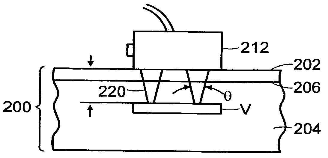
[0351]FIGS. 19A-27C illustrate various systems for delivering radiation in parallel to a plurality of target portions 214. The arrays of these figures are typically fixed focus arrays for a particular depth d. This depth may be changed either by using a different array having a different focus depth, by selectively changing the position of the array relative to the surface of the patient's skin or to target volume V or by controlling the amplitude-phase distribution of the incident radiation. FIGS. 28-31 show various optical lens arrays which may be used in conjunction with the scanning or deflector systems of FIGS. 32A-37 to move to successive one or more focused portions 214 within target volume V. Finally, FIGS. 38 ...

example 3

Enhanced-Penetration Channels and Optical Clearance of Pig Skin In Vitro

[0396] A lattice of damage islets was created in the stratum corneum of farm pig skin using a standard flash-arc-lamp system that emits in the 650-1200 nm band (StarLux Rs™, Palomar Medical Technologies, Burlington, Mass.) and a damage islet mask consisting of carbon particles in a film which was applied to the surface of the skin. Furthermore, to determine optical clearance of treated areas of pig skin specimens, a 40% solution of glucose in water was applied to the surface of the specimen. Optical clearance refers to a change in optical properties of the tissue which makes it more transparent in the optical range by reducing light scattering. Permeation of the skin by glucose or glycerin increases the optical clearance by reducing the refractive index differences between the interstitial solution and the intercellular matrix proteins collagen and elastin.

[0397] In a first set of experiments, an approximatel...


PUM


Abstract

Methods of treatment of tissue with electromagnetic radiation (EMR) to produce lattices of EMR-treated islets in the tissue are disclosed. Also disclosed are devices and systems for producing lattices of EMR-treated islets in tissue, and cosmetic and medical applications of such devices and systems.

Description

RELATED APPLICATIONS [0001] This application claims benefit of priority to U.S. Provisional Application No. 60 / 561,052, filed Apr. 9, 2004, U.S. Provisional Application No. 60 / 614,382, filed Sep. 29, 2004, and U.S. Provisional Application No. 60 / 641,616, filed Jan. 5, 2005; is a continuation-in-part of U.S. patent application Ser. No. 10 / 465,137, filed Jun. 19, 2003, which claims benefit of priority to U.S. Provisional Application No. 60 / 389,871, filed Jun. 19, 2002; is a continuation-in-part of U.S. patent application Ser. No. 10 / 033,302, filed Dec. 27, 2001, which claims benefit of priority to U.S. Provisional Application No. 60 / 258,855, filed Dec. 28, 2000; and is a continuation-in-part of U.S. patent application Ser. No. 10 / 080,652, filed Feb. 22, 2002, which claims priority to U.S. Provisional Application No. 60 / 272,745, filed Mar. 2, 2001.BACKGROUND OF THE INVENTION [0002] 1. Field of the Invention [0003] The invention relates to the treatment of tissue with electromagnetic ra...

Claims


Application Information

Patent Timeline
Patent Type & Authority Applications(United States)
IPC IPC(8): A61N5/06A61B17/00A61B18/00A61B18/20A61H39/00
CPCA61B18/203A61B2017/00765A61B2018/00005A61B2018/00452A61N2/00A61H39/002A61H2201/10A61N1/00A61B2018/0047A61B2018/00476A61B2018/2023A61B2018/20355
Inventor ALTSHULER, GREGORY B.YAROSLAVSKY, ILYAEROFEEV, ANDREI V.SMIRNOV, MIKHAIL Z.CHILDS, JAMES J.
Owner PALOMAR MEDICAL TECH
Why Eureka
Try Eureka