
Solid state multi frequency fluorometric measurements system and method

a fluorometric measurement and multi-frequency technology, applied in the field of frequency domain measurements, can solve the problems of increasing the potential for radio frequency distortion of decay, not seeing substantial application, and not having a viable solution, so as to reduce the time required, reduce the cost and complexity of the system, and improve the sensitivity and time resolution

Active Publication Date: 2006-02-02
HORIBA INSTR
View PDF7 Cites 8 Cited by
  • Summary
  • Abstract
  • Description
  • Claims
  • Application Information

AI Technical Summary

Benefits of technology

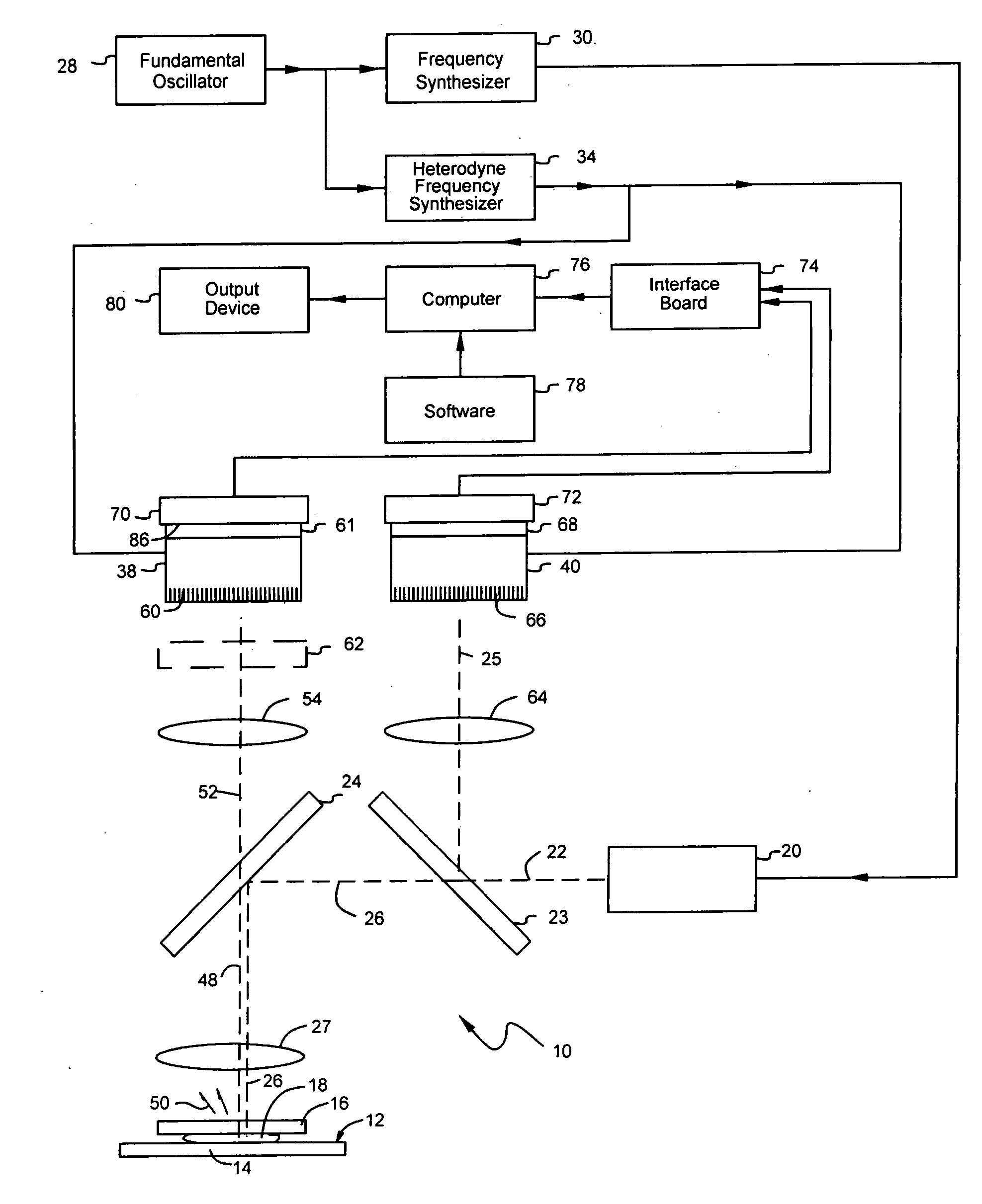
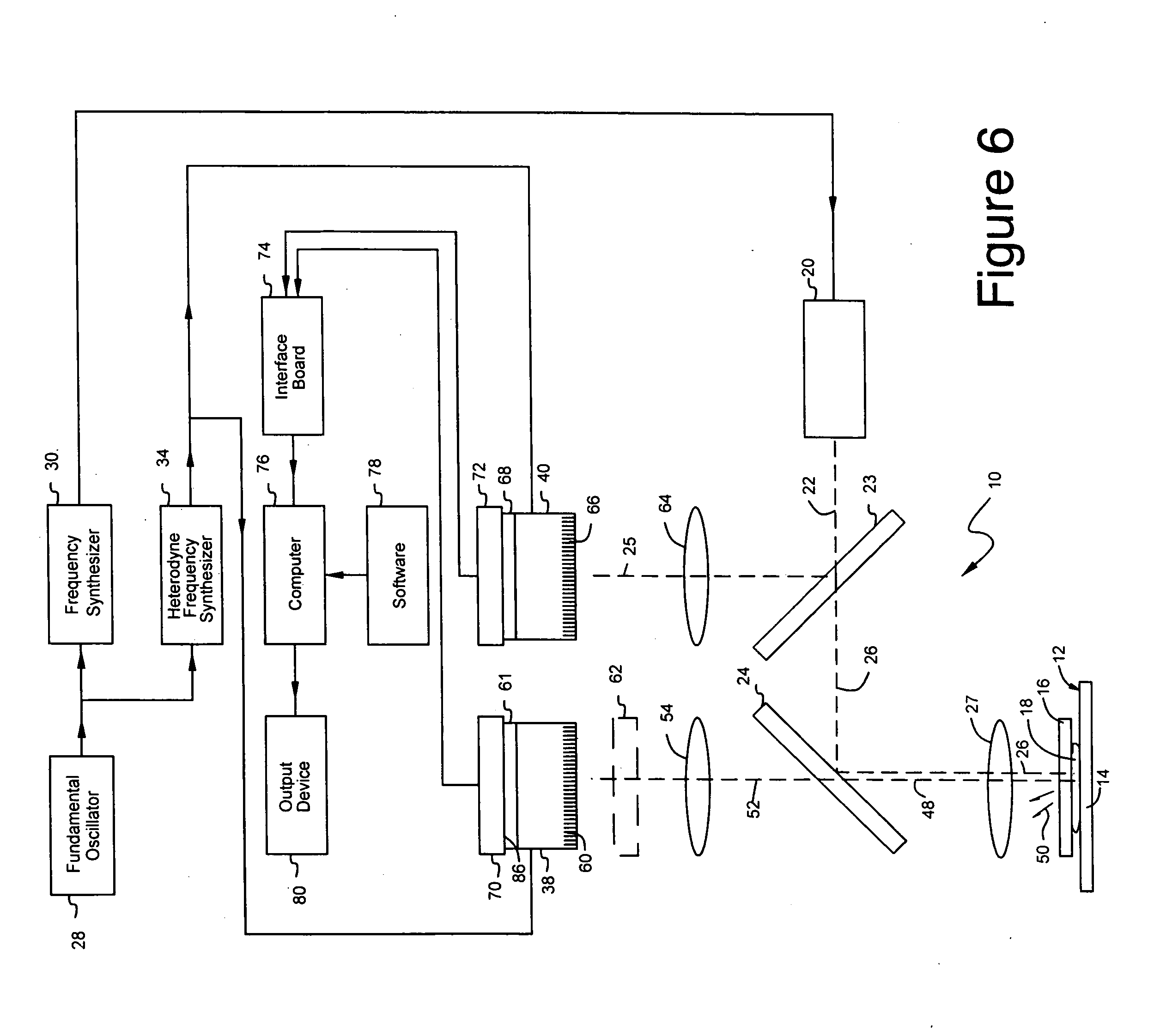
[0016] In principle, the inventive system provides a method of luminescence time-resolved measurement which, compared to prior art systems, greatly reduces the time required to observe protein interactions, while simultaneously reducing the cost and complexity of the system, while improving both sensitivity and time resolution. In particular, in accordance with the invention, a fluorescence measurement system particularly suited for imaging and making other fluorescence measurements for proteins comprises a 295 nm LED as an excitation source, a frequency domain fluorometer or TCSPC instrument, a sample illuminated by this excitation source, and a detector sensitive to a range of wavelengths of interest, for example those in the range of about 295-450 nm. The informational output which is obtained using such a system contains unique information on protein dynamics. Such protein dynamics include the measurement of energy transfer, lifetimes, folding, and various energy activities. While, as alluded to above, the use of laser diodes has been considered in the past such diodes are relatively uneconomical and available wavelengths are limited. In addition, while the application of light emitting diodes to frequency-domain fluorescence microscopy has also been considered in the past, generally, such devices have capacitances which are too large to enable them to successfully implement frequency-domain or even time correlated single photon counting measurements.
[0018] In addition, the present invention provides measurements which are independent of changes in fluorophore concentration due to the effects of photobleaching. At the same time, the ease of measurement, the availability of time discrimination and kinetic rates together with unambiguous calibration increase the attractiveness of the inventive method.

Problems solved by technology

While fluorometric frequency domain fluoremetricers methods using semiconductor laser diodes in a frequency domain configuration are known, for example from U.S. Pat. No. 5,196,709 of Berndt, the same have not seen substantial application on account of inherent limitations flowing from problems associated with the frequency domain detection and characteristics of the laser sources used therein.
Some work recently has been done using LEDs in the visible, but the same is not a viable solution due to slow response time.
In addition to these problems, the lower repetition rate of a flashlamp, typically in the range of about 40 kilohertz increases the potential for radio frequency distortion of decays due to higher voltage switching and poorer pulse-to-pulse temporal reproducibility.

Method used


Image

  • Solid state multi frequency fluorometric measurements system and method
  • Solid state multi frequency fluorometric measurements system and method
  • Solid state multi frequency fluorometric measurements system and method

Examples


Embodiment Construction

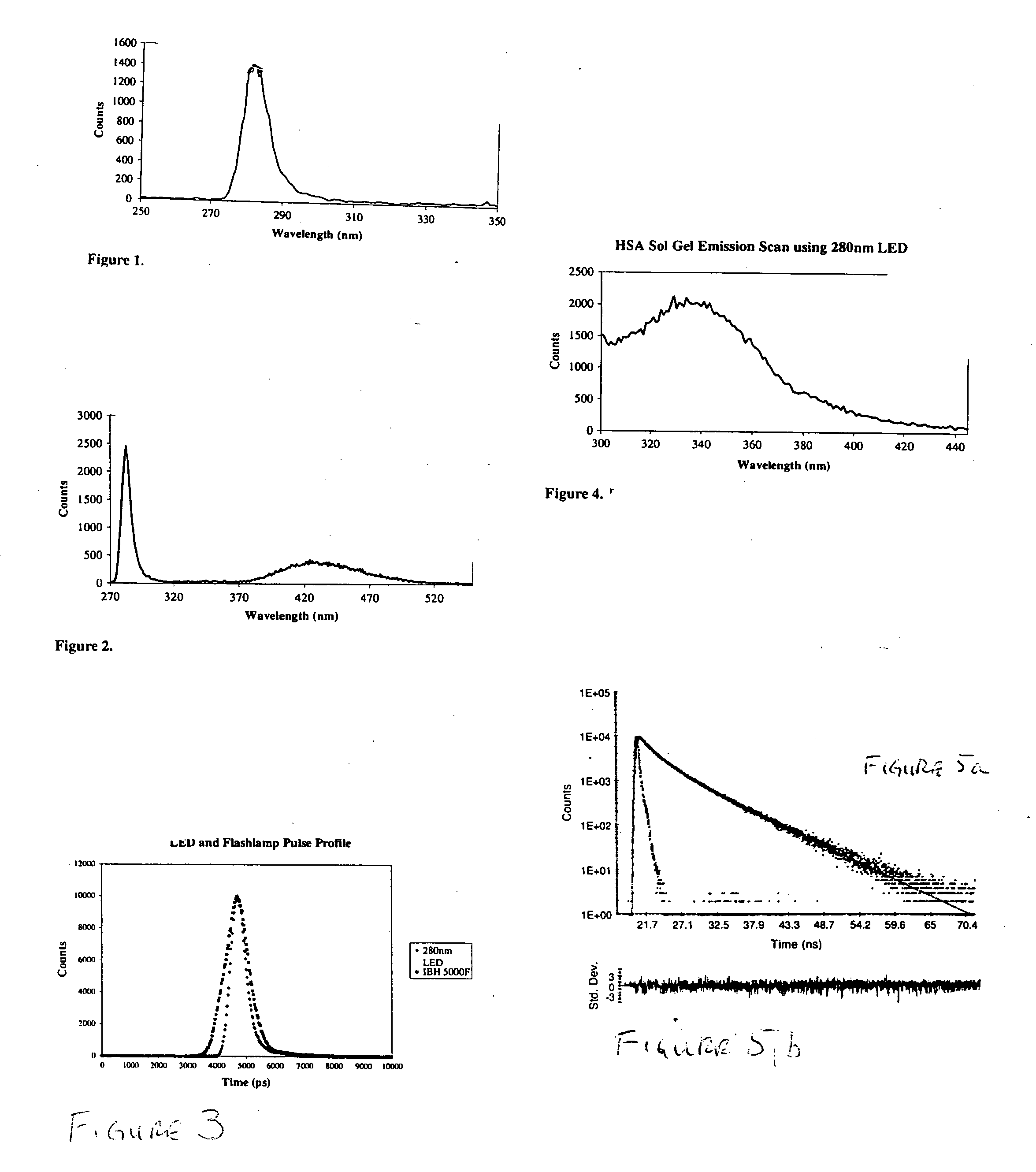
[0028] In accordance with the present invention, fluorescence decay is measured by the observation of the native fluorescence of the proteins, such as the amino acids tyrosine and tryptophan. This represents significant advantages as compared to the use of an extrinsic fluorescent probe which carries with it the possibility of disturbing the local environment. As noted above, the present invention has significant advantages as compared to the prior art techniques for exciting intrinsic protein fluorescence, including synchrotron radiation, mode locked lasers and flashlamps. The present invention allows the accumulation of data at a faster rate as well as simplified, less labor-intensive data generation.

[0029] More particularly, in accordance with the present invention, fluorescence measurements of protein intrinsic fluorescence, excited using a light emitting diode operating with an output wavelength below 350 and more particularly below 300 nanometers may be taken on human serum a...


PUM

PropertyMeasurementUnit
wavelengthsaaaaaaaaaa
frequenciesaaaaaaaaaa

Abstract

A method of spectrographic measurement is disclosed. The method generates light energy using a solid state low capacitance excitation source, the light energy being caused to fall on a sample to be assayed, causing the sample to output an output optical signal. The method generates a plurality of modulation frequencies, and a plurality of heterodyne frequencies to form a set of heterodyne signals at the heterodyne frequencies. Each of the heterodyne frequencies is associated with one of the modulation frequencies. Coupling the modulation frequencies to the excitation source, causes the excitation source to generate excitation energy modulated in intensity in proportion to the modulation frequencies. A sampling a portion of the substantially incoherent excitation energy forms a reference substantially incoherent excitation signal. Focusing the output optical signal as an image modulated with the plurality of modulation frequencies on an image intensifier enables the formation of an intensified image modulated with the plurality of modulation frequencies, receiving the intensified image modulated with the plurality of modulation frequencies on a multielement optical detector.

Description

TECHNICAL FIELD [0001] The present invention relates to frequency domain measurements employing using a low cost, low complexity 295 nm light modulated in intensity with a plurality of frequencies, employing a solid-state light emitting source, and is particularly suited for the investigation of certain biological entities. BACKGROUND [0002] The characteristics of light emanating from an object or a material may be advantageously detected and analyzed in order to determine characteristics of the object or material under examination. For many years, spectrographic techniques have been used to perform analysis of materials ranging from human blood and other biological materials to slag from a crucible. For example, it has been known that wavelengths of light absorbed by a material, as well as the wavelengths of light emitted by a material during an excited state, such as combustion, both indicate the composition of the material. Today, analytic instruments in industrial, scientific an...

Claims


Application Information

Patent Timeline
Patent Type & Authority Applications(United States)
IPC IPC(8): G01N21/64
CPCG01J3/10G01J3/433G01N21/6458G01N21/6408G01J3/4406
Inventor MCLOSKEY, DAVIDBAKER, GLENNMATTHEIS, JIMATZENI, SAL
Owner HORIBA INSTR
Learn More