System for jetting phosphor for optical displays

a technology of optical display and phosphor, which is applied in the manufacture of electrode systems, cold cathode manufacturing, electric discharge tubes/lamps, etc., can solve the problems of mesh deformation, high cost of techniques, and limited screen printing methods, and achieves fast response time, simple and less expensive systems, and increased accuracy and speed

Inactive Publication Date: 2006-02-09
NORDSON CORP
View PDF59 Cites 40 Cited by
  • Summary
  • Abstract
  • Description
  • Claims
  • Application Information

AI Technical Summary

Benefits of technology

[0008] The present invention provides an improved method of distributing phosphor onto a plasma screen. An embodiment includes a noncontact jetting system that accurately applies, on-the-fly, a viscous phosphor dot into a plasma cell of the screen. The system permits dispensed weight or dot size of the applied phosphor to be adjusted by changing either the tempera

Problems solved by technology

While meeting with some success, screen printing methods remain limited in that the mesh becomes deformed as a result of repeated printing during manufacture.
This technique can thus be expensive, in that mesh must frequently be exchanged during production.
Moreover, the accuracy of the emulsion techniques used by screen printing is problematic, resulting in bridging between plasma cells.
These disadvantages make it difficult to form an economically feasible phosphor layer that is capable of providing a highly precise plasma display.
This method must be repeated for each layer of red, green and blue phosphor, however, which complicates the processes of co

Method used


Image

  • System for jetting phosphor for optical displays
  • System for jetting phosphor for optical displays
  • System for jetting phosphor for optical displays

Examples


Embodiment Construction

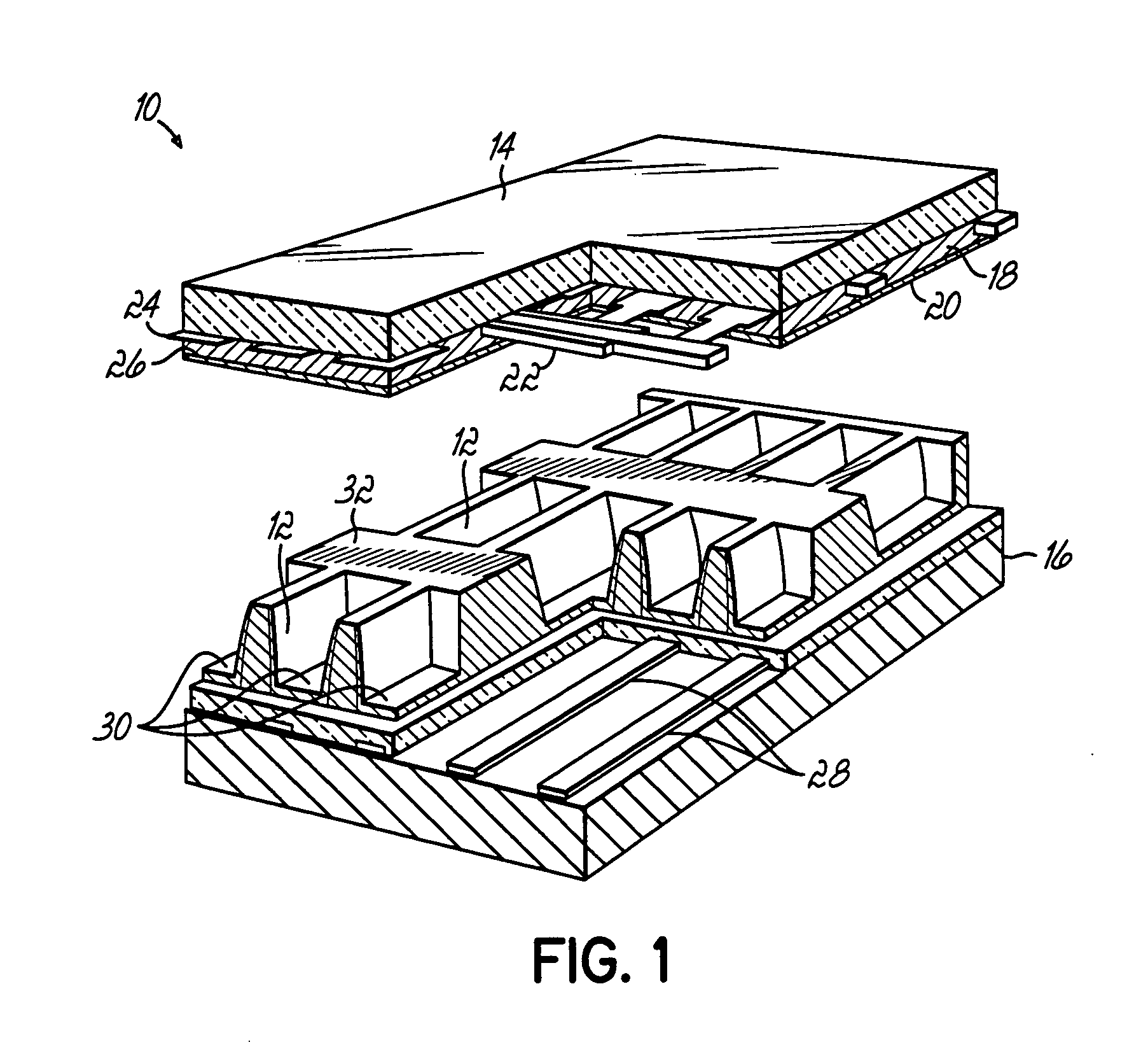
[0027]FIG. 1 is a plasma panel 10 having a network of plasma cells 12 located between a coplanar arrangement of front and rear plates 14 and 16, respectively. The front plate 14 comprises a glass substrate on which a dielectric layer 18 and thereon a protective layer 20 are provided. The protective layer 20 is typically made of MgO, and the dielectric layer 18 is made, for example, of glass containing PbO. Parallel, strip-type discharge electrodes 24 and auxiliary electrodes 22 are provided on the glass plate 14 and are covered by the dielectric layer 18. The electrodes 22 and 24 are typically made from metal. The dielectric layer 18 provided over the transparent discharge electrodes 24 prevents direct discharge between the electrodes 24, thus mitigating the formation of an arc or other undesired effect during ignition of the discharge.

[0028] In the panel embodiment shown in FIG. 1, an ultraviolet light emitting layer 26 is provided on the protective layer 20 and converts radiation...


PUM

PropertyMeasurementUnit
Temperatureaaaaaaaaaa
Weightaaaaaaaaaa
Flow rateaaaaaaaaaa

Abstract

A jetting system has a jetting dispenser mounted for relative motion with respect to a plasma panel. A control is operable to cause the jetting dispenser to jet a phosphor droplet that is applied to a cell of the panel. A feedback signal indicative of the placement and size of the dot is communicated to a control. The size, velocity offset and/or placement of subsequently applied phosphor dots is controlled by heating and cooling, or adjusting a piston stroke in the jetting dispenser in response to the feedback.

Description

FIELD OF THE INVENTION [0001] The present invention generally relates to light emitting panels, and more particularly, to methods and equipment used to fabricate the same. BACKGROUND OF THE INVENTION [0002] Plasma screens produce glare-free color images with exceptional resolution, despite having relatively large and compact displays. The desirable display features of plasma screens are attributable to their unique construction, which typically comprises two glass panels that sandwich a grid of plasma cells. The sealed cells contain rare gases, e.g., argon, neon or xenon, in addition to red, green and blue phosphors. Electrodes positioned within the glass panels ionize the gas to form plasma. Ultraviolet light produced by the plasma reacts with the colored phosphors to produce visible light in the form of reconstituted video images. [0003] Conventional methods used for forming the light emitting phosphor layers include screen printing technologies. In screen printing, a screen mesh ...

Claims


Application Information

Patent Timeline
IPC IPC(8): B05D5/12B05D5/06B05C11/00
CPCB05C11/1034H01J9/2277
Inventor BABIARZ, ALEC J.LEWIS, ALAN R.SAGAMI, YOSUKESURIAWIDJAJA, FLORIANA
Owner NORDSON CORP
Why Eureka
Try Eureka