Methods of controlling the properties of abrasive particles for use in chemical-mechanical polishing slurries

a technology of chemical-mechanical polishing and abrasive particles, which is applied in the direction of lanthanide oxides/hydroxides, chemistry apparatus and processes, etc., can solve the problems of difficult to avoid the introduction of contaminants, difficult to obtain a narrow distribution of appropriately sized abrasive particles, and high energy consumption, so as to improve the polishing of sti structures and reduce defects

Inactive Publication Date: 2006-02-16
FERRO CORP
View PDF18 Cites 25 Cited by
  • Summary
  • Abstract
  • Description
  • Claims
  • Application Information

AI Technical Summary

Benefits of technology

[0015] The present invention provides methods of controlling the properties of abrasive particles produced via hydrothermal synthesis for use in chemical-mechanical polishing slurries. As used in the present specification and in the appended claims, the phrase “hydrothermal treatment” refers to the direct synthesis of inorganic particles from aqueous solutions at relatively low temperature (e.g., from about 100° C. to about 374° C., which are the boiling and critical points of water) and relatively moderate pressure (e.g., up to about 15 Mpa). The methods of the present invention allow for control over properties

Problems solved by technology

For example, it tends to be energy intensive and thus relatively expensive.
In addition, it is very difficult to avoid the introduction of contaminants during the calcination and subsequent milling processes.
Finally, it is difficult to obtain a narrow distribution of appropriately sized abrasive particles.
It is well known that CMP slurries containing contaminants and / or over-sized abrasive particles can result in undesirable surface scratching during polishing.
The production of abrasive particles meeting these requirements by conventional calcination and milling techniques is extremely difficult and often not economically feasible.
Unfortunately, however, abrasive particles formed by conventional hydrothermal treatment processes tended not to provide desired high polishing rates, at least when compared to abrasive particles having the same diameter (typically referred to in the art as “secondary particle size”) formed by calcination and milling.

Method used


Image

  • Methods of controlling the properties of abrasive particles for use in chemical-mechanical polishing slurries
  • Methods of controlling the properties of abrasive particles for use in chemical-mechanical polishing slurries
  • Methods of controlling the properties of abrasive particles for use in chemical-mechanical polishing slurries

Examples


example 1

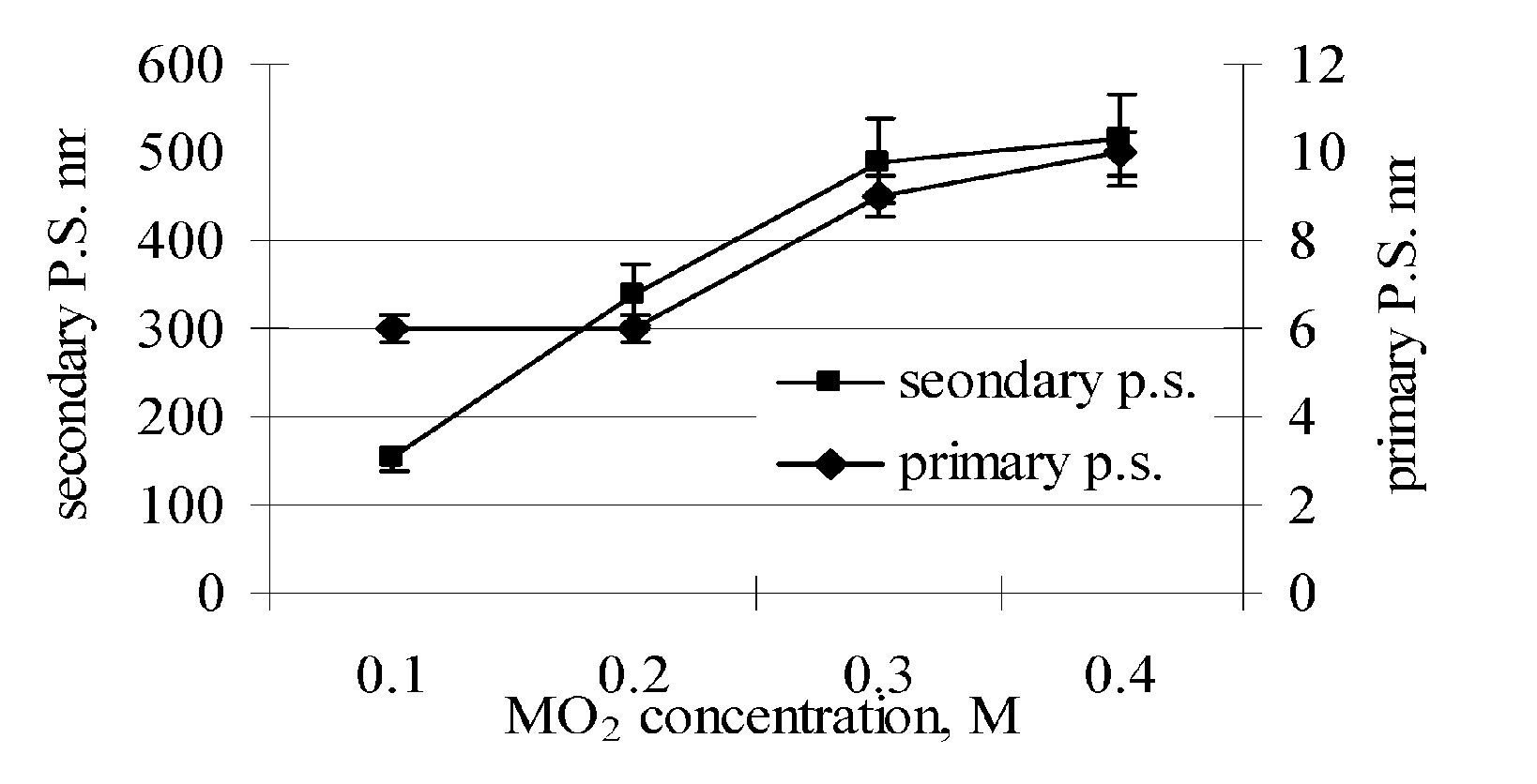
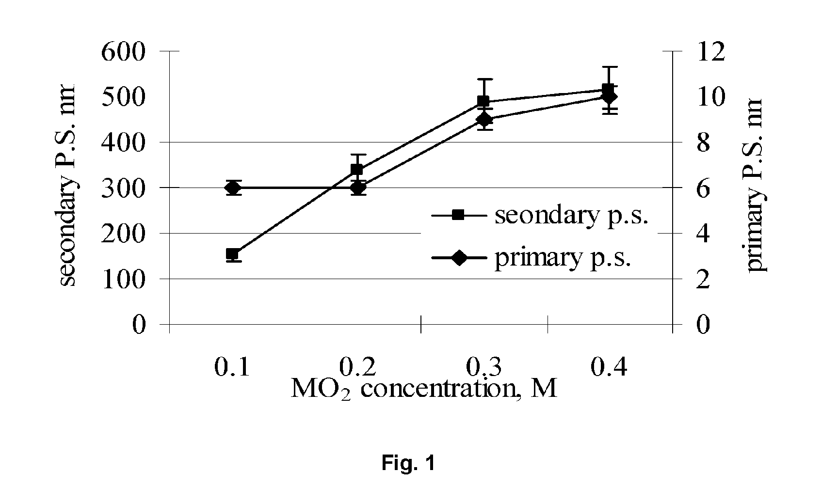
[0080] In a 1000 ml plastic bottle, 41.6 grams of (NH4)2Ce(NO3)6 (ammonium cerium (IV) nitrate) was dissolved in 500 ml deionized H2O (DI-water) and 1.2 grams CH3COCH2OCCH3 (acetyl acetone) to form a solution. 2.4 grams of Ti[OCH(CH3)2)]4 (titanium (IV) isopropoxide) was added to the solution followed by the addition of 36 grams of C2H5NH2 (ethylamine) with stirring. A sufficient quantity of DI-water was then added to reach a final volume of 800 ml. The solution was stirred for 5 minutes and then transferred to a clean 1000 ml stainless steel vessel. The stainless steel vessel was closed and sealed, shaken for 5 minutes, and then placed into a furnace and heated at 300° C. for 6.0 hours. The stainless steel vessel was then removed from the furnace and allowed to cool to room temperature. The reaction product formed in the vessel was transferred to a clean 1000 ml plastic bottle. As shown in FIG. 1, the reaction product consisted of a dispersion of CeO2 (cerium oxide) particles havin...

example 3

[0082] A dispersion of cerium oxide particles was formed using the same materials and procedures as set forth in Example 1, except that no acetyl acetone (CH3COCH2OCCH3) was used. The cerium oxide particles thus formed had a narrow size distribution (D50=80 nm; D90 =97 nm; and D10=60 nm) similar to the cerium oxide particles formed in Example 1, but the average crystallite size was only 90 Å.

example 4

[0083] Four chemical-mechanical polishing slurries were formed using cerium oxide particles. Slurry A consisted of 100 parts by weight of the cerium oxide nanoparticle dispersion formed in Example 1. Slurry B was identical to Slurry A, except that the cerium oxide nanoparticle dispersion formed in Example 2 was used instead of the cerium oxide nanoparticle solution formed in Example 1. Slurry C was identical to Slurry A, except that the cerium oxide nanoparticle dispersion formed in Example 3 was used instead of the cerium oxide nanoparticle solution formed in Example 1. Slurry D was identical to Slurry A, except that the cerium oxide nanoparticle dispersion comprised conventional calcined cerium oxide (Ferro Electronic Material Systems SRS-616A) having an average particle size of D50=141 nm dispersed in water at a pH of 10.0. Identical TEOS SiO2 (silicon dioxide) wafers were polished using Slurries A, B, C, and D, respectively. The polishing was performed using a Strasbaugh 6EC pol...


PUM

PropertyMeasurementUnit
Temperatureaaaaaaaaaa
Sizeaaaaaaaaaa

Abstract

The present invention provides methods of controlling the properties of abrasive particles produced via hydrothermal synthesis for use in chemical-mechanical polishing slurries. In accordance with the methods of the invention, variables such as cerium salt concentration, dopant solution concentration, hydrothermal medium pH, hydrothermal temperature and processing duration are controlled to produce particles having the desired properties and shapes. The abrasive particles formed in accordance with the method of the invention can be used to produce CMP slurries that provide substantial improvements in the polishing of STI structures and a reduction in defects.

Description

CROSS-REFERENCE TO RELATED APPLICATIONS [0001] This application is a continuation-in-part of co-pending U.S. application Ser. No. 10 / 851,684, filed May 21, 2004, which is a continuation-in-part of U.S. application Ser. No. 10 / 255,136, now U.S. Pat. No. 6,818,030, filed Sep. 25, 2002, which is a continuation-in-part of U.S. application Ser. No. 09 / 992,485, now U.S. Pat. No. 6,596,042, filed Nov. 16, 2001.BACKGROUND OF THE INVENTION [0002] 1. Field of Invention [0003] The present invention relates to methods of controlling the properties of abrasive particles for use in chemical-mechanical polishing slurries. [0004] 2. Description of Related Art [0005] Chemical-mechanical polishing (CMP) slurries are used, for example, to planarize surfaces during the fabrication of semiconductor chips and the like. CMP slurries typically include reactive chemical agents and abrasive particles dispersed in a liquid carrier. The abrasive particles perform a grinding function when pressed against the su...

Claims


Application Information

Patent Timeline
IPC IPC(8): C03C15/00B44C1/22C01F17/235
CPCB82Y30/00H01L21/3212C01G23/04C01G23/053C01P2002/60C01P2002/76C01P2004/51C01P2004/62C01P2004/64C01P2006/90C03C19/00C09C1/3653C09G1/02C09K3/1409C09K3/1436C09K3/1463H01L21/31053C01F17/0043C01F17/235
Inventor FENG, XIANGDONGHER, YIE-SHEIN
Owner FERRO CORP
Why Eureka
Try Eureka