Stent and process for producing the same

a technology of intralum and stent, which is applied in the field of intralum stent, to achieve the effects of reducing the formation of thrombosis, reducing the risk of twisting and/or tearing of polymer films, and excellent bendability

Inactive Publication Date: 2006-02-16
JAPAN STENT TECH CO LTD +1
View PDF10 Cites 228 Cited by
  • Summary
  • Abstract
  • Description
  • Claims
  • Application Information

AI Technical Summary

Benefits of technology

[0038] In the stent of the seventh invention, the outer polymer film and the inner polymer film covering the stent matrix are not bonded to the stent matrix so as to allow shift of the stent matrix relative to the outer polymer film and the inner polymer film so that the stent matrix expands while sliding between the outer polymer film and the inner polymer film. Therefore, the stent has no risk of twisting and/or tearing the polymer films. In addition, since the outer polymer film and the inner po

Problems solved by technology

However, this procedure has a problem of high possibilities that an acute phase block of a coronary artery is caused and that the portion treated by PTCA is narrowed again (so-called post-PTCA restenosis).
On the other hand, however, since metallic stent matrixes are foreign substances in human bod

Method used


Image

  • Stent and process for producing the same
  • Stent and process for producing the same
  • Stent and process for producing the same

Examples


example 1

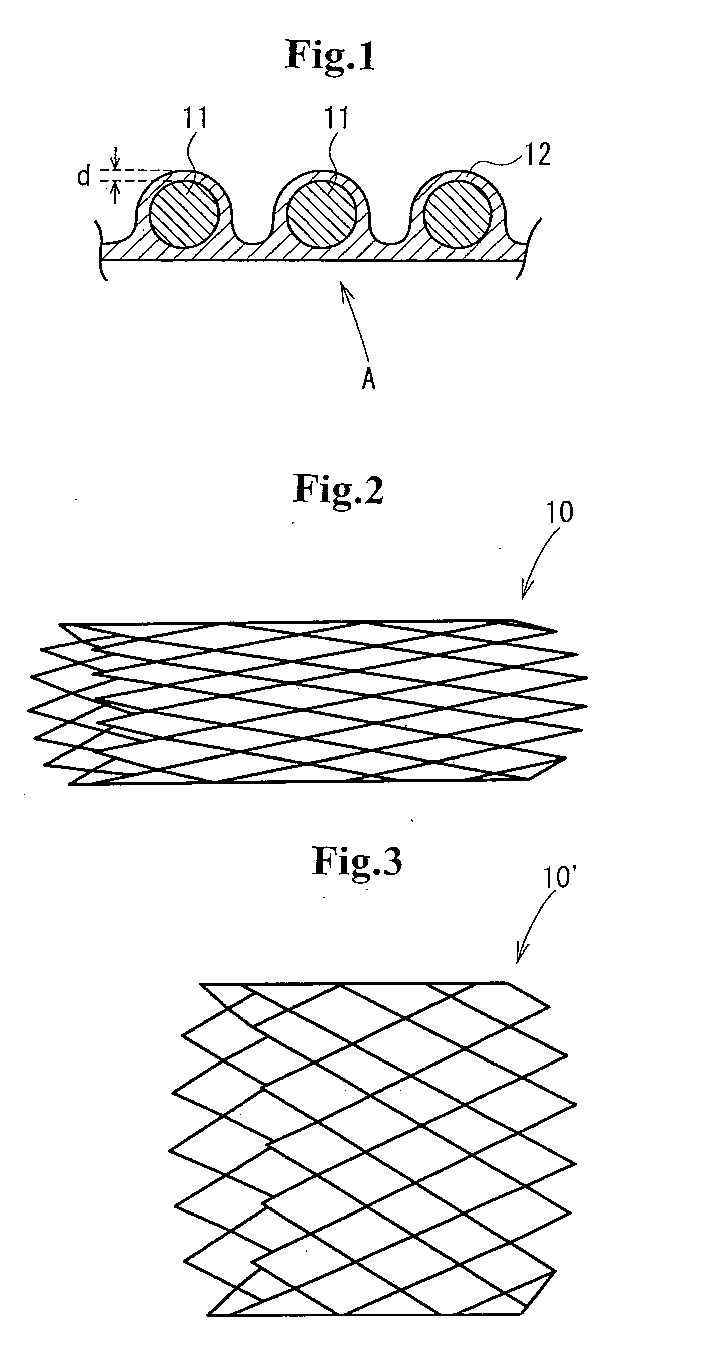
[0089] As the stent matrix, a mesh stent matrix 10 having a diameter of 4 mm, a length of 20 mm, and a thickness of 0.2 mm shown in FIG. 2 was employed.

[0090]FIG. 3 is a perspective view of the metallic stent matrix 10′ after being expanded. The metallic stent matrix 10′ in this state has a diameter of 8 mm, a length of 20 mm, and a thickness of 0.2 mm.

[0091] A stent was produced by coating the entire surfaces of the metallic stent matrix 10 with a segmented polyurethane polymer layer. As described concretely, a mandrel made of SUS316 was impregnated into a polyurethane solution to form a polyurethane layer for coating a cylindrical outer surface of the mandrel. The metallic stent matrix which was slightly expanded was overlaid on the polyurethane layer with significant pressure. The mandrel with the stent matrix was impregnated into the polyurethane solution to form a coating so that both the inner and outer peripheries of the stent matrix were coated. After laser machining, the ...

example 2

[0116] As the stent matrix, a mesh stent matrix 10 having a diameter of 3.2 mm, a length of 20 mm, and a thickness of 0.2 mm shown in FIG. 2 was employed.

[0117]FIG. 3 is a perspective view of the metallic stent matrix 10′ after being expanded. The metallic stent matrix 10′ in this state has a diameter of 8 mm, a length of 20 mm, and a thickness of 0.2 mm.

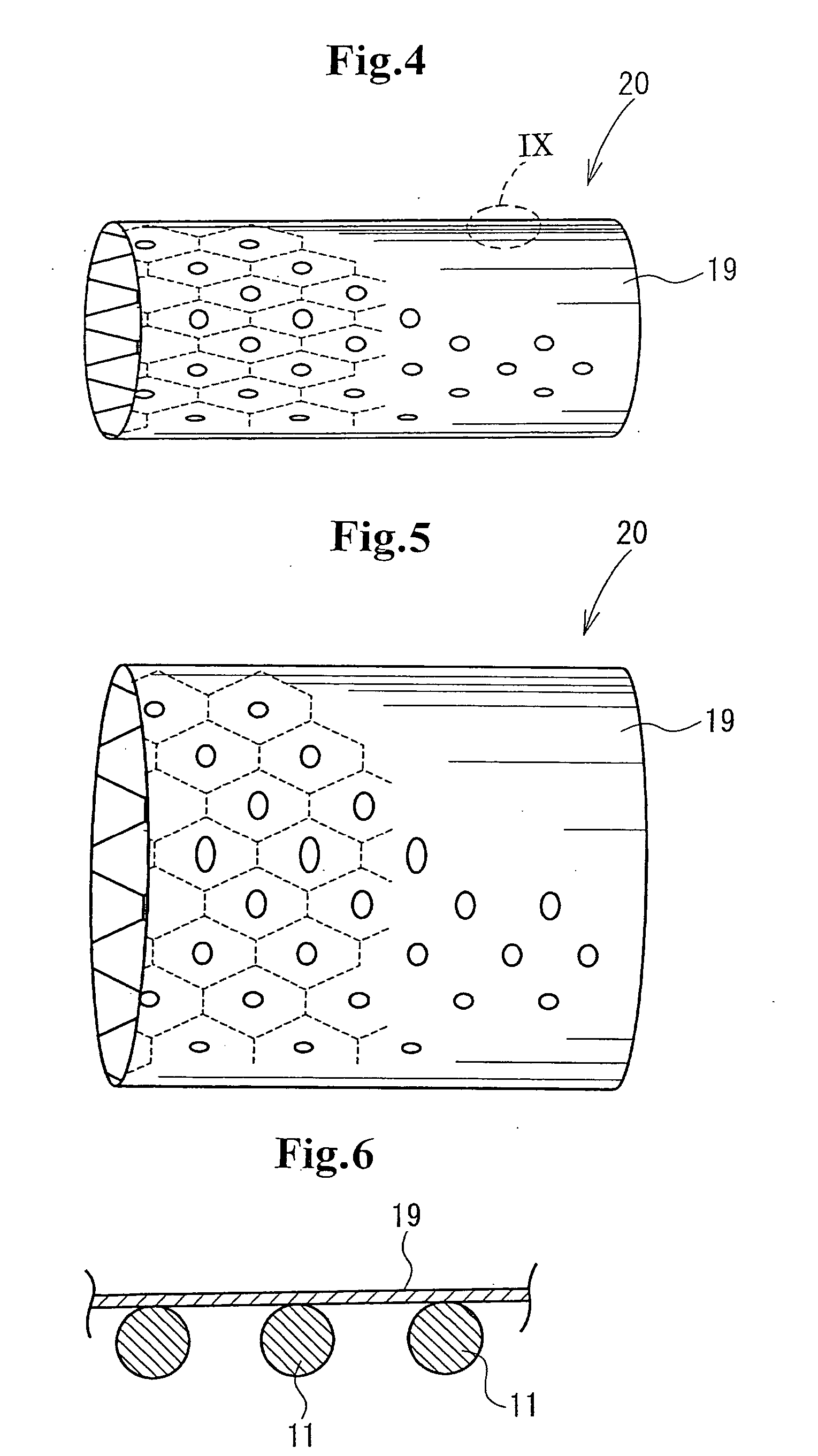
[0118] A stent was produced by coating the inner periphery and the outer periphery of the metallic stent matrix 10 with segmented polyurethane polymer films 19. As described concretely, a mold having an inner diameter of 3.5 mm was rotated at 6000 rpm and a polyurethane solution was supplied into the mold while moving the injection position along the axial direction of the mold, and heating the polyurethane solution in the mold at 60° C., thereby forming a polymer film as an outer layer having a thickness of 50 μm. After the stent matrix was inserted into the mold, a polyurethane solution was supplied to form a film while rotating...

example 4

[0135] As the stent matrix, a mesh stent matrix 10 having a diameter of 4 mm, a length of 20 mm, and a thickness of 0.2 mm shown in FIG. 2 was employed.

[0136]FIG. 3 is a perspective view of the metallic stent matrix 10′ after being expanded. The metallic stent matrix 10′ in this state has a diameter of 8 mm, a length of 20 mm, and a thickness of 0.2 mm.

[0137] A stent was produced by coating the inner periphery and the outer periphery of the metallic stent matrix 10 with segmented polyurethane polymer films. As described concretely, a mandrel having a diameter of 3.8 mm and made of stainless steel was impregnated into a polyurethane solution, was then pulled up, and was dried so as to form a cylindrical coating of the polyurethane having 30 μm. The metallic stent matrix which was slightly expanded was overlaid on the coating with significant pressure. The mandrel with the stent matrix was impregnated into the polyurethane solution, was then pulled up, and was dried so as to form a ...


PUM

PropertyMeasurementUnit
Thicknessaaaaaaaaaa
Diameteraaaaaaaaaa
Diameteraaaaaaaaaa

Abstract

A stent comprising a tubular stent matrix of which diameter is extendable and a flexible polymer layer covering the stent matrix. The polymer layer is closely attached to and covers the entire surface of the stent matrix. Since the flexible polymer layer closely covers the entire surface of the stent matrix not only the outer periphery of the stent matrix, the stent has no problem of causing allergic to metal, stimulus of tissues due to metal, and rust development. Since the inner periphery of the stent is a flat and smooth surface covered by the polymer layer without convexes and concaves, the formation of thrombus can be inhibited well. There is no problem of drift between the polymer layer and the stent matrix, thereby maintaining the positional relationship between the stent matrix and the polymer layer before and after the expansion of the stent.

Description

TECHNICAL FIELD [0001] The present invention relates to a stent (intraluminal graft) which is recently used for intravascular therapy and surgical operation, particularly to enlarge a coronary stenosis, a carotid stenosis, a biliary duct, or an esophagus or to block an aneurysm and to a process for producing the same. More particularly, the present invention relates to a stent comprising a plurality of tubular stent matrixes of which diameter is extendable and which are aligned at intervals in the longitudinal direction thereof and are covered and united by a polymer film and to a process for producing the same. BACKGROUND ART [0002] Conventionally, ischemic heart diseases are generally treated by percutaneous transluminal coronary angioplasty (PTCA), that is, a procedure of introducing a balloon catheter to, for example, a narrowed part through a lumen of a blood vessel and, after that, inflating a balloon with liquid such as normal saline solution. However, this procedure has a pr...

Claims


Application Information

Patent Timeline
IPC IPC(8): A61F2/90A61F2/82A61F2/07A61L31/10A61L31/16
CPCA61F2/90A61F2210/0076A61F2210/0004A61F2250/0067A61L31/10A61L31/16A61L2300/00B29C41/042B29C41/14B29C41/20B29C41/22B29K2995/0059B29K2995/006B29L2031/753A61F2002/072
Inventor NAKAYAMA, YASUHIDENISHI, SHOGONEMOTO, YASUSHIOKAMOTO, YOSHIHIRO
Owner JAPAN STENT TECH CO LTD
Why Eureka
Try Eureka