
Piston ring and thermal spray coating used therein, and method for manufacturing thereof

Active Publication Date: 2006-02-23
RIKEN CO LTD
View PDF7 Cites 26 Cited by
  • Summary
  • Abstract
  • Description
  • Claims
  • Application Information

AI Technical Summary

Benefits of technology

[0005] Accordingly, an object of the present invention is to provide a piston ring having excellent wear resistance, scuffing resistance and peeling resistance with little attackability on mating members.
[0008] As a result of intense research in view of the above objects, the inventors have found that it is possible to form a uniform thermal spray coating having a fine microstructure, (a) by thermally spraying a composite powder comprising chromium carbide particles having desired particle sizes and a Ni—Cr alloy or a Ni—Cr alloy and Ni as main components, or (b) by thermally spraying a combination of such composite powder and another desired metal or alloy powder; and that a piston ring having such a thermal spray coating have excellent wear resistance, scuffing resistance and peeling resistance with little attackability on a mating member. The present invention has been completed based on these findings.

Problems solved by technology

In diesel engines used under particularly severe conditions, thermal spray coatings of cermets are used, but when combined, for instance, with cylinder liners of ferrite-rich, soft cast iron (FC200 to 300) having a tensile strength of 300 MPa or less, the cylinder liners disadvantageously suffer from large wear near top dead points.
Though these thermal spray coatings are considerably improved in wear resistance, scuffing resistance and peeling resistance, their attackability on mating members has not been sufficiently lowered yet.
Thus, the resultant thermal spray coating has an uneven microstructure.
Also, because the coating structure is uneven, the surface roughness of the thermal spray coating cannot be reduced to a desired level or less even by grinding, resulting in wearing a mating cylinder liner.
Further, because there are locally extremely hard portions composed only of chromium carbide, an inlaid piston ring having a layer thermally sprayed in a center groove on an outer peripheral surface disadvantageously have steps on groove edges after finish-working of the outer peripheral surface.

Method used


Image

  • Piston ring and thermal spray coating used therein, and method for manufacturing thereof
  • Piston ring and thermal spray coating used therein, and method for manufacturing thereof
  • Piston ring and thermal spray coating used therein, and method for manufacturing thereof

Examples


example 1

(1) Test Piece

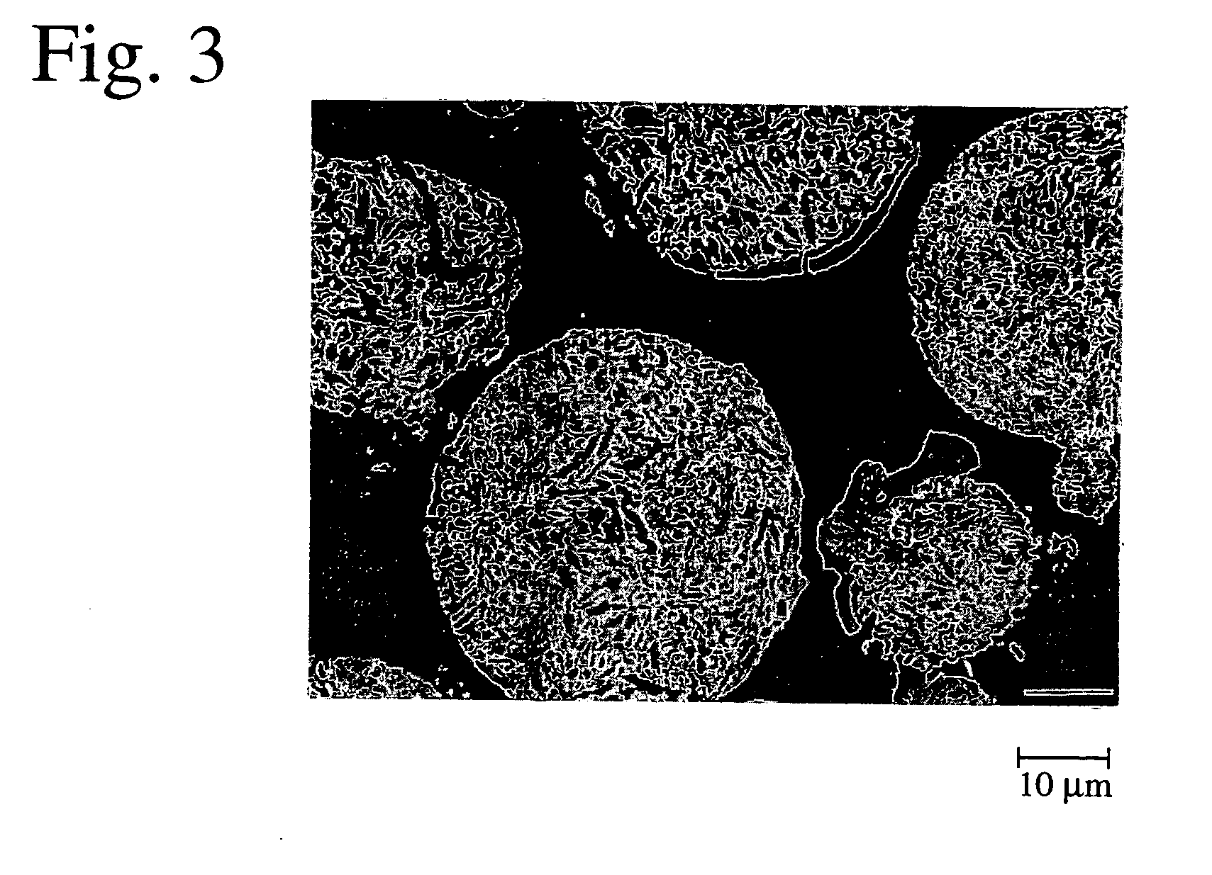
[0059] A rectangular prism body of 5 mm in height, 5 mm in width and 20 mm in length was produced from the same spheroidal graphite cast iron (FCD600) as in a piston ring substrate, and one of its end surfaces (5 mm×5 mm) was ground to a curved surface having a radius of curvature R of 10 mm. This curved surface was blasted with #30 alumina particles to a surface roughness (10-point average roughness Rz) of 20 μm, to provide a test piece substrate. Rapidly solidified fine particles (“Sulzer Metco 5241,” available from Sulzer Metco) were used as thermal spray powder. Sulzer Metco 5241 is fine particles which are obtained by melting a material having a composition of Cr:Ni:C=54:39:7 (% by mass) and rapidly solidifying the melt, with Cr and C forming chromium carbide and Ni and Cr forming a Ni—Cr alloy by melting and rapid solidification. Namely, Sulzer Metco 5241 has a structure in which crystallized chromium carbide particles are dispersed in a Ni—Cr alloy. FIG. 3 is ...

example 2

[0072] A test piece corresponding to a piston ring was produced in the same manner as in Example 1, except for using as a thermal spraying powder CRC-410 (mass ratio of chromium carbide particles: Ni—Cr alloy=70:30, available from Praxair Technology, Inc.) produced by a rapid solidification method. The finished thermal spray coating had a surface roughness (10-point average roughness Rz) of 2.64 μm.

[0073] Pores in the thermal spray coating had an area ratio of 5% (thus porosity of 5% by volume) and an average diameter of 3 μm. The chromium carbide particles in a portion of the thermal spray coating excluding pores had an area ratio of 63% and an average particle size of 2.8 μm. The chromium carbide particles had dendritic and non-equiaxial shapes peculiar to solidified structures as in Example 1. The hardness of the thermal spray coating measured in the same manner as in Example 1 was 815 Hv0.1 on average, with its standard deviation of 142 Hv0.1.

[0074] The same wear test as in Ex...

example 3

[0075] 100 parts by mass of a mixed powder of 75% by mass of chromium carbide particles having an average particle size of 3.6 μm and 25% by mass of a Ni—Cr alloy powder (mass ratio of Ni / Cr=80 / 20) having an average particle size of 4.5 μm was mixed with 15 parts by mass of polyvinyl alcohol as a binder, granulated by spray drying, classified, and sintered at 800° C., to produce a granulated and sintered powder of chromium carbide particles / Ni—Cr alloy powder shown in FIG. 8. The granulated and sintered powder had a particle size under 325 mesh.

[0076] A curved surface of a rectangular prism body made of the same spheroidal graphite cast iron (FCD600) as in Example 1 was blasted and subjected to an activation treatment in the same manner as in Example 1 immediately before thermal spraying. Using an HVAF spraying gun (available from Intelli-Jet), the high-velocity flame spraying of the above granulated and sintered powder was conducted onto a curved surface of the rectangular prism b...


PUM

PropertyMeasurementUnit
Lengthaaaaaaaaaa
Lengthaaaaaaaaaa
Fractionaaaaaaaaaa

Abstract

The piston ring of the present invention comprises a thermal spray coating comprising chromium carbide particles having an average particle size of 5 μm or less, and a matrix metal composed of a Ni—Cr alloy or a Ni—Cr alloy and Ni at least on an outer peripheral surface, said thermal spray coating having an average pore diameter of 10 μm or less and a porosity of 8% or less by volume. A piston ring having excellent wear resistance, scuffing resistance and peeling resistance with little attackability on a mating member is obtained by forming a homogeneous thermal spray coating having a fine microstructure.

Description

FIELD OF THE INVENTION [0001] The present invention relates to a piston ring, a thermal spray coating used thereon, and a method for producing such a piston ring, particularly to a piston ring having excellent wear resistance, scuffing resistance and peeling resistance and also low attackability on mating members that it is suitable for internal combustion engines, compressors, etc., a thermal spray coating used thereon, and a method for producing such a piston ring. BACKGROUND OF THE INVENTION [0002] As internal combustion engines have increasingly higher performance such as higher power, it is demanded that piston rings have excellent wear resistance and scuffing resistance. Thus, outer peripheral surfaces of piston rings made of cast iron or steel have been subjected to surface treatments such as hard chromium plating, nickel composite plating, nitriding, chromium nitride ion plating and thermal spraying, etc. In diesel engines used under particularly severe conditions, thermal s...

Claims


Application Information

Patent Timeline
IPC IPC(8): B32B3/06B32B5/14B22D7/00B22F5/00B22F7/02B22F3/10B22F7/04C23C4/06
CPCC23C4/06Y10T428/12083Y10T428/12028Y10T428/12937Y10T428/12493Y10T428/12042Y10T428/12Y10T428/12014Y10T428/12944Y10T428/249957Y10T428/249956Y10T428/24997Y10T428/249978Y10T428/249987
Inventor OBARA, RYOUTAKIGUCHI, KATSUMI
Owner RIKEN CO LTD
Features
  • Generate Ideas
  • Intellectual Property
  • Life Sciences
  • Materials
  • Tech Scout
  • Unparalleled Data Quality
  • Higher Quality Content
  • 60% Fewer Hallucinations
Learn More