Apparatus for measuring a mechanical quantity

a mechanical quantity and apparatus technology, applied in the direction of force measurement using piezo-resistive materials, instruments, reradiation, etc., can solve the problems of large measuring errors, small noise detection accuracy, and large noise of strain sensors, so as to reduce the power consumption of sensors, compensate for small changes in mechanical quantity sensors, and reduce noise. the effect of the sensor

Inactive Publication Date: 2006-03-02
HITACHI LTD
View PDF8 Cites 48 Cited by
  • Summary
  • Abstract
  • Description
  • Claims
  • Application Information

AI Technical Summary

Benefits of technology

[0011] This invention offers an advantage that, even when a mechanical quantity sensor is operated by using a small electricity supplied through electromagnetic induction or microwaves, noise picked up by the sensor can be made very small. Since all the circuits are formed in a small area on the same silicon substrate, a current that would otherwise be induced by a phase difference of radio waves when RF feeding (supply of electricity in the form of radio wave energy) is performed can be prevented from being generated in the sensor, making it possible for a sensor to perform its intended sensing operation even when a small electric power is used. That is, when activating the circuits by using an induced current as a power source, it is essential to reduce the power consumption of the sensor. In that case, data from the sensor is not buried in noise, allowing for correct measurement.
[0012] Further, since the Wheatstone bridge circuit of the above arrangement and construction

Problems solved by technology

When a strain sensor and a mechanical quantity sensor applying the strain sensor, such as pressure sensor, vibration sensor and acceleration sensor, are connected to a circuit that uses an electricity supplied through electromagnetic induction or microwaves to transmit the result of measurement, however, the following problems characteristic of the mechanical quantity sensor arise.
First, the strain sensor has a very small output for a measured strain and is very vulnerable to noise as compared with other sensors such as temperature sensor.
At this time, if any noise, even at a small level, enters the circuit, it can cause large measuring errors.
Further, when the electricity supplied by electromagnetic induction or microwaves is used, an amount of electricity that can be supplied to the strain sensor is very limited and is required to be set two or more orders of magnitude smaller tha

Method used


Image

  • Apparatus for measuring a mechanical quantity
  • Apparatus for measuring a mechanical quantity
  • Apparatus for measuring a mechanical quantity

Examples


Embodiment Construction

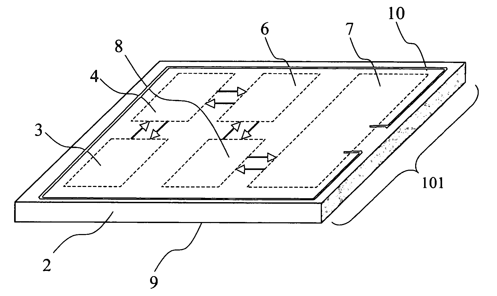
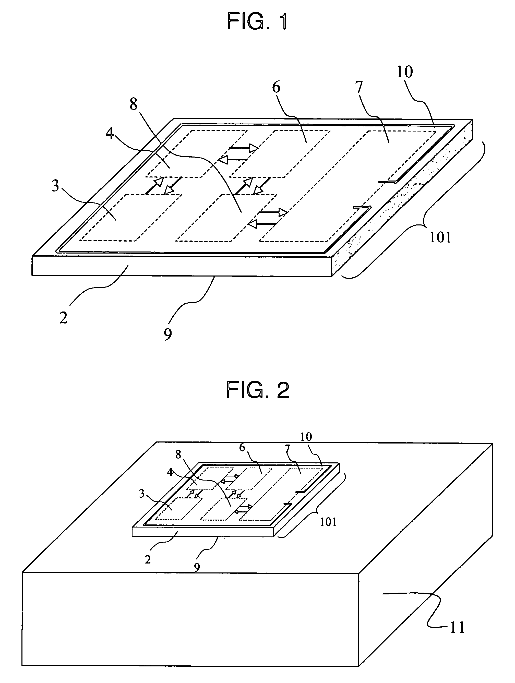
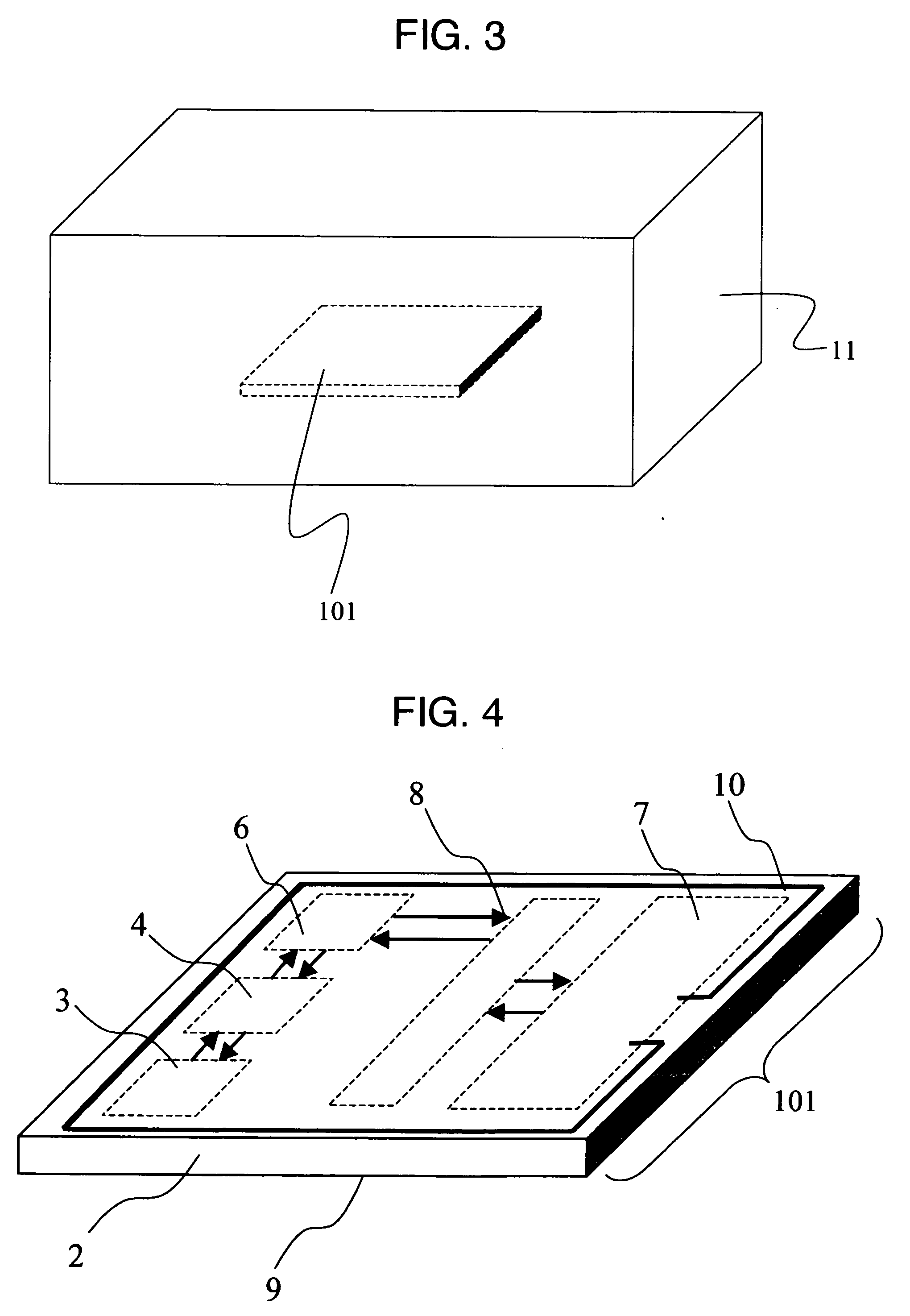
[0057] Embodiments of this invention will be disclosed. A strain measuring system that operates on an electricity supplied by electromagnetic induction or microwaves can be formed on one and the same silicon substrate.

[0058] Embodiments of this invention will be described by referring to FIG. 1 through FIG. 10. FIG. 1 shows a mechanical quantity measuring apparatus 1 as a first embodiment of this invention. This embodiment is a mechanical quantity measuring apparatus having formed on one and the same single crystal silicon substrate 2 at least a strain sensor 3 utilizing a piezoresistive effect, a strain sensor amplifier group 4, an analog / digital converter 6, a rectification / detection / modulation-demodulation circuit 7, a communication control unit 8, a bonding surface 9, and an antenna 10. In the following description the silicon substrate 2 and a group of thin films formed on the silicon substrate 2 are together called a chip 101. Although the antenna 10 may be formed in large si...


PUM


Abstract

A mechanical quantity measuring apparatus is provided which can make highly precise measurements and is not easily affected by noise even when it is supplied an electricity through electromagnetic induction or microwaves. At least a strain sensor and an amplifier, an analog/digital converter, a rectification/detection/modulation-demodulation circuit, and a communication control circuit are formed in one and the same silicon substrate. Or, the silicon substrate is also formed at its surface with a dummy resistor which has its longitudinal direction set in a particular crystal orientation and which, together with the strain sensor, forms a Wheatstone bridge. With this arrangement, even when a current flowing through the sensor is reduced, measured data is prevented from being buried in noise, allowing the sensor to operate on a small power and to measure a mechanical quantity with high precision even when it is supplied electricity through electromagnetic induction or microwaves.

Description

BACKGROUND OF THE INVENTION [0001] The present invention relates to an apparatus capable of measuring a mechanical quantity and outputting a measured value wirelessly. [0002] What is generally called an RF tag has been developed which uses an electricity supplied through electromagnetic induction to active a circuit and thereby transmit a preset ID number wirelessly and which is beginning to be applied to a goods distribution management and a management of admission tickets. Attempts are currently under way to connect a physical quantity sensor to such an ID tag. For example, as disclosed in JP-A-2001-187611, a temperature sensor is connected to an RF tag circuit on a printed circuit board, and the temperature sensor mounted on the printed circuit board is then entirely molded with plastic to form an ID tag with a sensor. BRIEF SUMMARY OF THE INVENTION [0003] When a strain sensor and a mechanical quantity sensor applying the strain sensor, such as pressure sensor, vibration sensor a...

Claims


Application Information

Patent Timeline
IPC IPC(8): H01L29/84G01L1/18G01B7/16G01S13/74
CPCG01L1/18
Inventor OHTA, HIROYUKISUMIGAWA, TAKASHI
Owner HITACHI LTD
Why Eureka
Try Eureka