Heterodyning time resolution boosting method and system

Inactive Publication Date: 2006-03-23
LAWRENCE LIVERMORE NAT SECURITY LLC
View PDF3 Cites 49 Cited by
  • Summary
  • Abstract
  • Description
  • Claims
  • Application Information

AI Technical Summary

Benefits of technology

[0013] One aspect of the present invention includes a method for increasing the temporal resolution of an optical detector measuring the intensity versus time of an intrinsic optical signal S0(t) of a target having frequency f, so as to enhance the measurement of high frequency components of S0(t), said method comprising: illuminating the target with a set of n phase-differentiated channels of sinusoidally-modulated intensity Tn(t), with n≧3 and modulation frequency fm, to produce a corresponding set of optically heterodyned signals S0(t)Tn(t); detecting a set of signals In(t) at the optical detector which are the optically heterodyned signals S0(t)Tn(t) reaching the detector but blurred by the detector impulse response D(t), expressed as In(t)={S0(t)Tn(t)}{circle around (×)}D(t)=Sord(t)+In,osc(t), where Sord(t) is an ordinary signal component and In,osc(t) is an oscillatory component comprising a down-shifted beat component and an up-shifted conjugate beat component; in a phase stepping analysis, using the detected signals In(t) to determine an ordinary signal Sord,det(t) to be used for signal reconstruction, and a single phase-stepped complex output signal Wstep(t) which is an isolated single-sided beat signal; numerically reversing the optical heterodyning by transforming Wstep(t) to Wstep(f) and Sord,det(t) to Sord,det(f) in frequency space, and up-shifting Wstep(f) by fM to produce a treble spectrum Wtreb(f), where Wtreb(f)=Wstep(f−fM); making the treble spectrum Wtreb(f) into a double sided spectrum Sdbl(f) that corresponds to a real valued signal versus time Sdbl(t); combining the double sided spectrum Sdbl(f) with Sord,det(f) to form a composite spectrum Sun(f); equalizing the composite spectrum Sun(f) to produce Sfin(f); and inverse transforming the equalized composite spectrum Sfin(f) into time space to obtain Sfin(t) which is the measurement for the intrinsic optical signal S0(t).
[0014] Another aspect of the present invention includes A computer program product comprising: a computer useable medium and computer readable code embodied on said computer useable medium for causing an increase in the temporal resolution of an optical detector measuring the intensity versus time of an intrinsic optical signal S0(t) of a target having frequency f, so as to enhance the measurement of high frequency components of S0(t) when the target is illuminated with a set of n phase-differentiated channels of sinusoidally-modulated intensity Tn(t), with n≧3 and modulation frequency fM, to produce a corresponding set of optically heterodyned signals S0(t)Tn(t), and a set of signals In(t) is detected at the optical detector which are the optically heterodyned signals S0(t)Tn(t) reaching the detector but blurred by the detector impulse response D(t), expressed as In(t)={S0(t)Tn(t)}{circle around (×)}D(t)=Sord(t)+In,osc(t), where Sord(t) is an ordinary signal component and In,osc(t) is an oscillatory component comprising a down-shifted beat component and an up-shifted conjugate beat component, said computer readable code comprising: computer readable program code means for using the detected signals In(t) to determine an ordinary signal Sord,det(t) to be used for signal reconstruction, and a single phase-stepped complex output signal Wstep(t) which is an isolated single-sided beat signal; computer readable program code means for numerically reversing the optical heterodyning by transforming Wstep(t) to Wstep(f) and Sord,det(t) to Sord,det(f) in frequency space, and up-shifting Wstep(f) by fM to produce a treble spectrum Wtreb(f), where Wtreb(f)=Wstep(f−fM); computer readable program code means for making the treble spectrum Wtreb(f) into a double sided spectrum Sdbl(f) that corresponds to a real valued signal versus time Sdbl(t); computer readable program code means for combining the double sided spectrum Sdbl(f) with Sord,det(f) to form a composite spectrum Sun(f); computer readable program code means for equalizing the composite spectrum Sun(f) to produce Sfin(f); and computer readable program code means for inverse transforming the equalized composite spectrum Sfin(f) into time space to obtain Sfin(t) which is the measurement for the intrinsic optical signal S0(t).
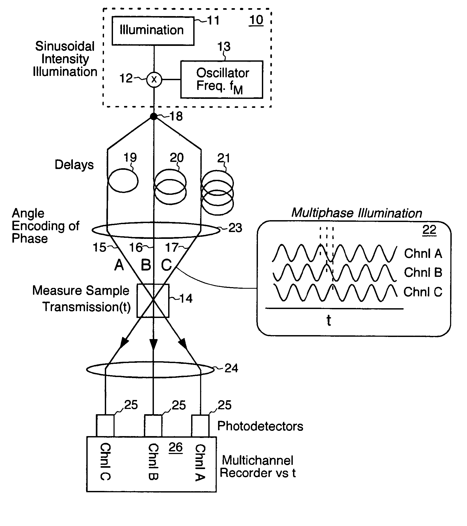
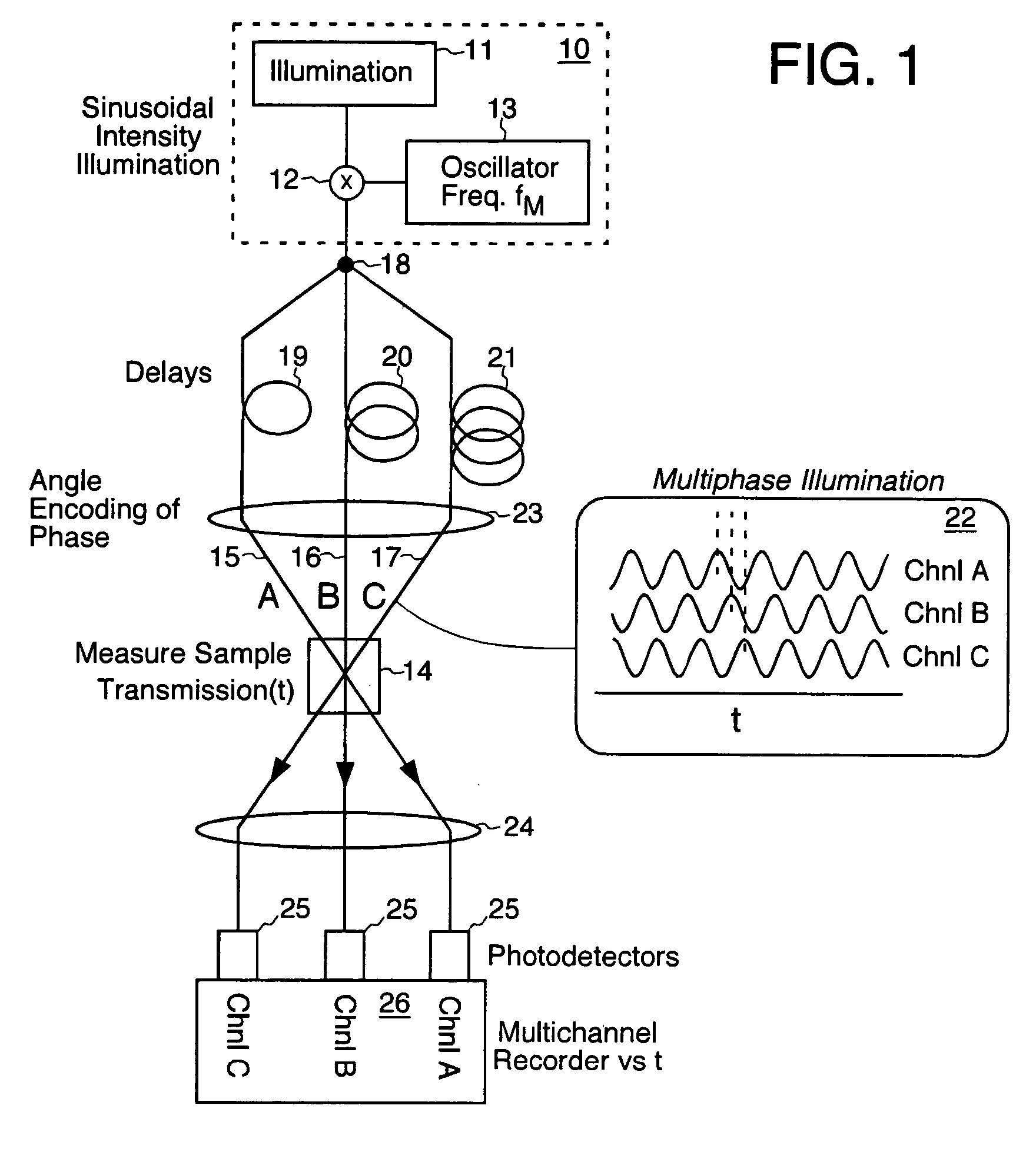
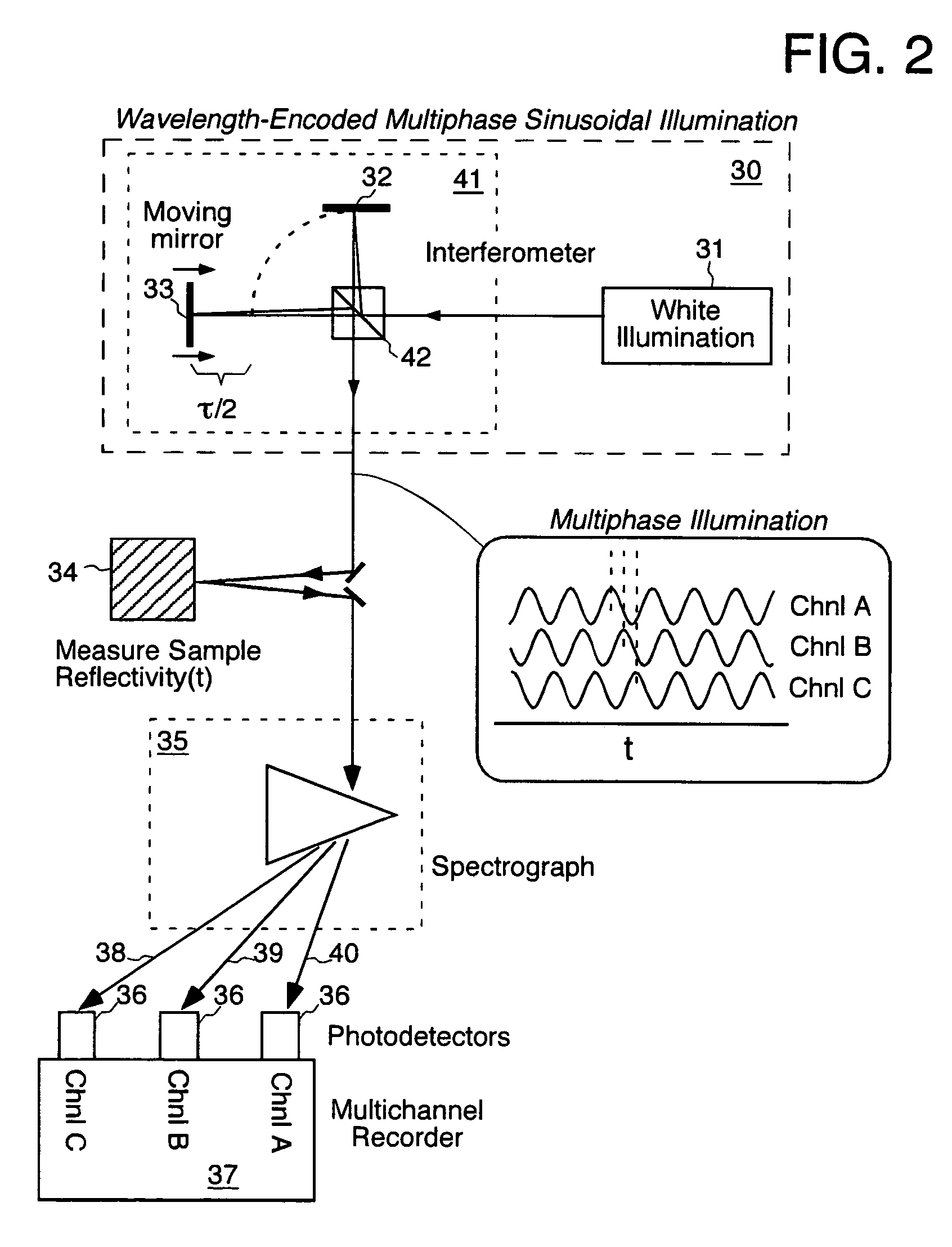
[0017] The present invention enhances the ability of a detector to measure the high frequency components of a time varying signal S0(t) by sinusoidally modulating it at a frequency fM prior to its detection, and to do so at several values of modulation phase φn, where n is called a phase stepping index. The modulation process can be represented by a transmission function Tn(t): Tn(t)=(0.5){1+γn cos(2πfmt+2πφn)}  Eqn. xx3 which varies sinusoidally versus the independent variable “t” and is phase shifted by φn, for the nth detecting channel of k channels. The (0.5) factor is unimportant here. The symbol γn is called the visibility and represents the degree of modulation, which is ideally unity but in practice less than this. The present invention multiplies the intrinsic signal by Tn(t), prior to the blurring action represented by the convolution in the following equation for the nth data channel: In(t)={Tn(t)S0(t)}{circle around (×)}D(t)  Eqn. xx4 A heterodyning effect occurs between the sinusoidal component of Tn(t) and S0(t), which creates up-shifted and down-shifted beat components. (The ordinary component Sord(t) is also produced.) The beat components are scaled replicas of S(f), but shifted in frequency, up and down, by amount fM. The up-shifted beat component is unlikely to survive detector blurring D(f). The down-shifted beat component in frequency space is: Wbeat(f)=(0.5)γS(f+fM)D(f)  Eqn. xx5 The down-shifted beats manifest high frequency information moved optically toward lower frequencies, where they are more likely to survive detector blurring. The present invention measures these beats, and then numerically reverses the heterodyning process during data analysis to recreate some of the original high frequency information. This is done by shifting the frequencies upward by fM, forcing the output to be purely real, and dividing out D(f) where appropriate.
[0018] Thus the present invention is capable of measuring frequencies near fM at better sensitivity than the detector used without modulation. If fM is chosen to lie on the shoulder of the ordinary response D(f) curve, then the effective frequency response of the instrument that combines the processed beat information with the ordinary signal, is expanded beyond D(f). Since resolving power is proportional to frequency response, the invention can improve (boost) the temporal resolving power of a detecting system, so that for the same record length a greater number of effective time bins are manifested.

Problems solved by technology

The problem is that due to the blurring of the electron beam on the phosphor screen, the number of independent time bins, which is a way of describing the instrument's time resolving power, is limited to about 200.
This is an insufficient resolving power for many science experiments, especially the measurement of shockwave phenomena performed at National laboratories.
The shockwave duration is very short-requiring very fast time resolution Δt.
Secondly, there is usually a large uncertainty in time between the trigger time that began the experiment and the arrival of the shockwave.
Another important instrument problem besides poor resolving power is instrument distortions and nonlinearities.
For example, the sweep speed of the electron beam writing the record in the streak camera can be non uniform, so that the time axis of the resulting record is non linear.
However, using valuable area on the phosphor screen for a fiducial grid removes channels available for the measurement.
Secondly, there can be distortions in the experimental apparatus, external to the signal recorder, such as variations in path length of long optical fibers between the target area and the signal recorders, which can produce unknown shifts in the time axis of one channel relative to another.
Typically, increasing the spectral resolution comes with a penalty of a larger dramatically more costly instrument.
Instrument distortions are also a significant problem with optical spectrographs.
For example, air convection, changes in the shape of the beam as it falls on the spectrograph entrance slit, and thermomechanical drifts in position of optical components can cause the wavelength axis to shift, producing instrumental errors.
A serious problem with phase stepping analysis that affects its accuracy occurs when the phase steps or visibilities are irregular or unknown in their detailed value.

Method used


Image

  • Heterodyning time resolution boosting method and system
  • Heterodyning time resolution boosting method and system
  • Heterodyning time resolution boosting method and system

Examples


Embodiment Construction

Encoding Phase-Differentiated Illumination Channels by Angle

[0067] Turning now to the drawings, FIG. 1 shows an embodiment of the invention that uses multiple phase-differentiated illumination channels, e.g. 15, 16, and 17, encoded by angle to measure a sample 14 transmission (or reflectivity) versus time. A light source 10 which has a sinusoidal variation of intensity versus time at frequency fM illuminates the sample. This could be created for example from a constant illumination source 11 by modulating light at an intensity modulator 12 controlled by a local oscillator signal 13 having frequency fM. This fM is referred to as a modulating or heterodyning frequency. The intensity modulator 12 could be implemented by an acousto-optical device commonly used in the laser sciences, which uses sound waves traveling in a crystal to diffract a beam of light away from a non-diffracted output into a diffracted output. Applying an oscillating voltage at frequency fM to the acousto-optic el...


PUM


Abstract

A method for enhancing the temporal resolving power of an optical signal recording system such as a streak camera or photodetector by sinusoidally modulating the illumination or light signal at a high frequency, approximately at the ordinary limit of the photodetector's capability. The high frequency information of the input signal is thus optically heterodyned down to lower frequencies to form beats, which are more easily resolved and detected. During data analysis the heterodyning is reversed in the beats to recover the original high frequencies. When this is added to the ordinary signal component, which is contained in the same recorded data, the composite signal can have an effective frequency response which is several times wider than the detector used without heterodyning. Hence the temporal resolving power has been effectively increased while maintaining the same record length. Multiple modulation frequencies can be employed to further increase the net frequency response of the instrument. The modulation is performed in at least three phases, recorded in distinct channels encoded by wavelength, angle, position or polarization, so that during data analysis the beat and ordinary signal components can be unambiguously separated even for wide bandwidth signals. A phase stepping algorithm is described for separating the beat component from the ordinary component in spite of unknown or irregular phase steps and modulation visibility values. This algorithm is also independently useful for analyzing interferograms or other phase-stepped interferometer related data taken with irregular or unknown phase steps, as commonly found in industrial vibration environments.

Description

I. CLAIM OF PRIORITY IN PROVISIONAL APPLICATION [0001] This application claims priority in provisional application No. 60 / 612,441, filed on Sep. 22, 2004, entitled “Heterodyning Time Resolution Boosting” by David John Erskine.[0002] The United States Government has rights in this invention pursuant to Contract No. W-7405-ENG-48 between the United States Department of Energy and the University of California for the operation of Lawrence Livermore National Laboratory.II. FIELD OF THE INVENTION [0003] The present invention relates to the high speed recording of signals, and more specifically the use of modulation to produce heterodyned beats in optical signals, the detection of which enhances signal measurement at high resolution. The present invention also relates to the high resolution recording of optical spectra, and more specifically the use of interferometric modulation to produce heterodyned beats, the detection of which enhances spectral measurement at high resolution. Furtherm...

Claims


Application Information

Patent Timeline
IPC IPC(8): G01B9/02
CPCG01J3/0208G01B2290/45G01J3/0224G01J3/10G01J3/453G01J9/04G01J2001/4242G01B9/02003G01B9/02044G01B9/02027G01B9/0209G01B9/02014G01B9/02043G01B2290/70G01J3/021
Inventor ERSKINE, DAVID JOHN
Owner LAWRENCE LIVERMORE NAT SECURITY LLC
Why Eureka
Try Eureka