Method and system for noise control in semiconductor spectroscopy system

a technology of semiconductor spectroscopy and noise control, applied in the direction of optical radiation measurement, instruments, spectrometry/spectrophotometry/monochromators, etc., can solve the problems of thermal noise, shot noise, and one drawback of semiconductor spectroscopy systems, and achieves the effects of high spectral brightness, size and efficiency, and long li

Active Publication Date: 2006-03-30
EXCELITAS TECH
View PDF17 Cites 29 Cited by
  • Summary
  • Abstract
  • Description
  • Claims
  • Application Information

AI Technical Summary

Benefits of technology

[0009] RIN, however, is not unique to semiconductor sources. It can impact the performance of solid state laser spectroscopy systems as well as systems based on tungsten-halogen bulbs or standard diodes. But, it tends to be larger in semiconductor sources, such as optically filtered SLEDS and SOAs. Thus, while semiconductor sources provide advantages such as long life, high spectral brightness, size, and efficiency, on one hand, they tend to have somewhat worse inherent noise characteristics, on the other.
[0010] The present invention is directed to an optical power control system for a semiconductor source spectroscopy system. As such, this optical power control system can be used to control power fluctuations in the tunable signal from the spectroscopy system and thus improve the noise performance of the system.
[0011] This general solution has advantages relative to other systems that simply detect reference power levels during the scan and then correct the detected signal after interaction with the sample, since this solution reduces requirements for coordinating the operation of the sample detectors and power or reference detectors.
[0017] In the preferred embodiment, the tunable filter is a micro-electro mechanical (MEMS) filter. In one implementation, this MEMS filter comprises two thin film dielectric mirror structures providing for a low loss, high finesse system that can provide efficient, narrow bandwidth operation.
[0020] Finally, in some implementations, a frequency reference system is further provided for detecting an instantaneous frequency of the tunable optical signal in order to further improve its performance and spectral accuracy. In one embodiment, for example, the amplitude detector system and frequency reference system are attached to a common optical bench.

Problems solved by technology

One drawback associated with semiconductor spectroscopy systems, however, is noise.
Shot noise is generated by random fluctuations of current flowing through the detector due to the quantum nature of charge.
Thermal noise results from electrons being freed in the detector due to thermal vibration and being indistinguishable from photoelectrons.
At higher optical powers, RIN dictates overall performance or signal-to-ratio (SNR), whereas at lower optical powers, shot noise usually tends to restrict the performance of the system.
Thus, while semiconductor sources provide advantages such as long life, high spectral brightness, size, and efficiency, on one hand, they tend to have somewhat worse inherent noise characteristics, on the other.

Method used


Image

  • Method and system for noise control in semiconductor spectroscopy system
  • Method and system for noise control in semiconductor spectroscopy system
  • Method and system for noise control in semiconductor spectroscopy system

Examples


Embodiment Construction

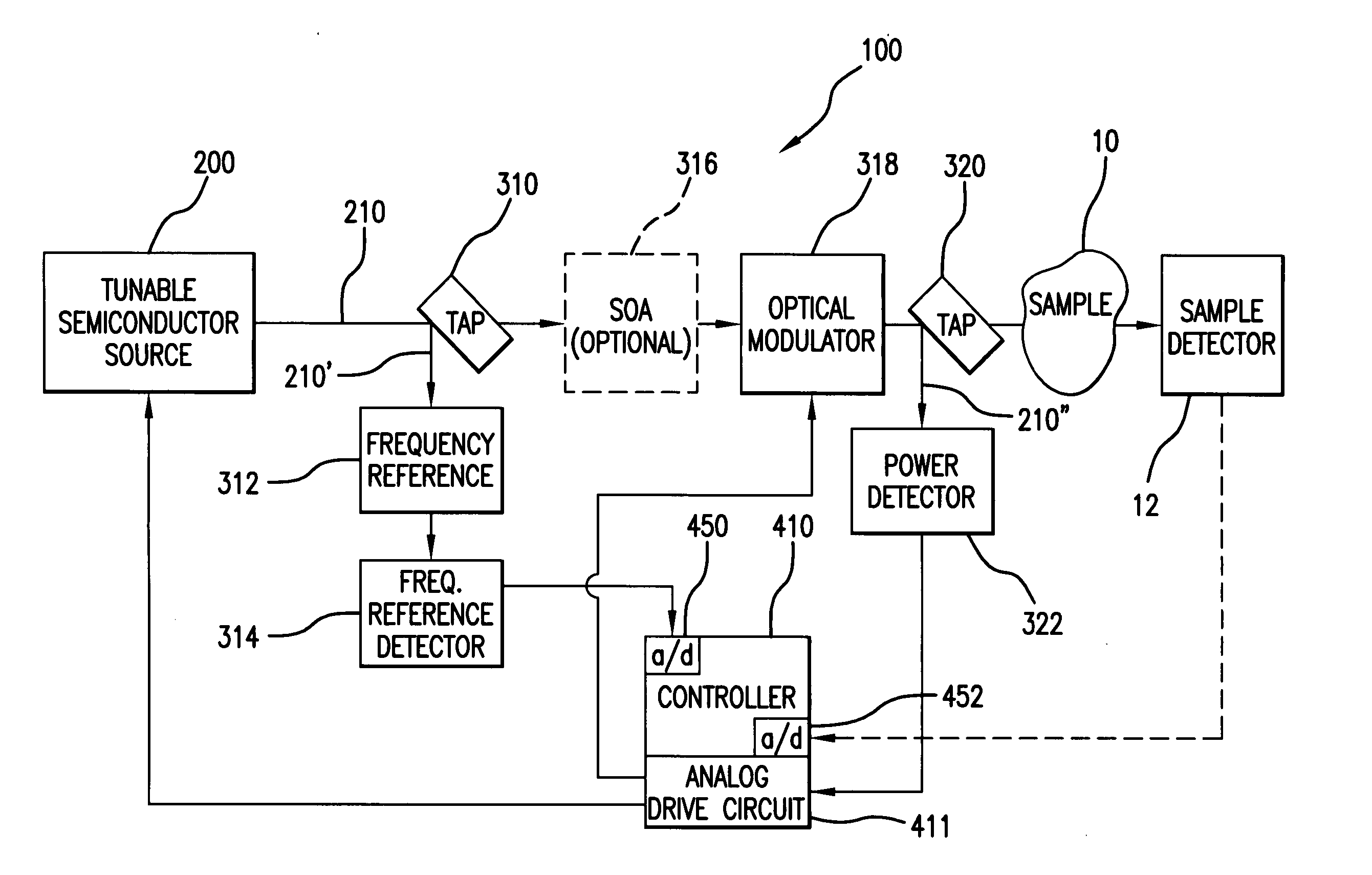
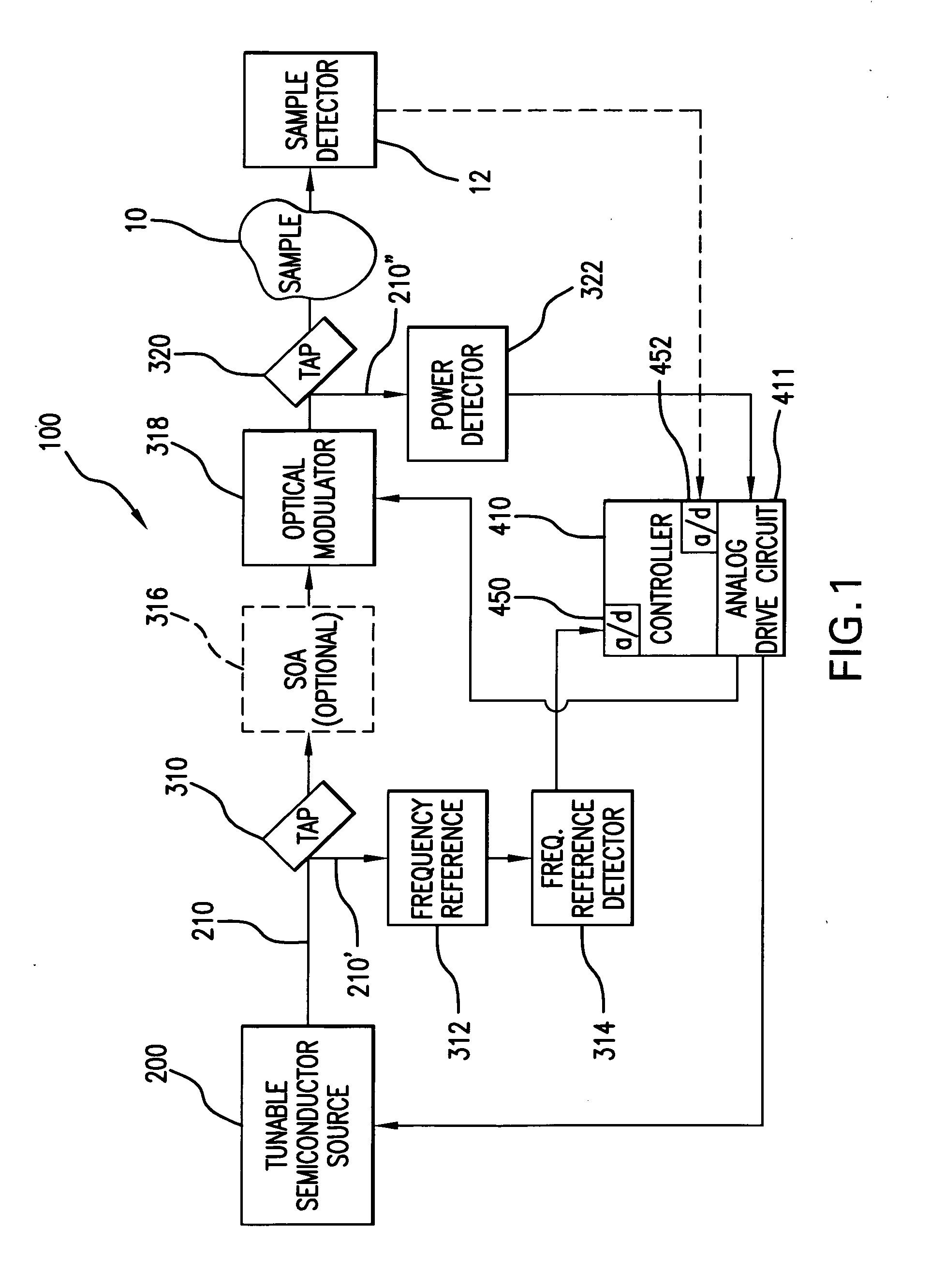
[0040]FIG. 1 shows a semiconductor source spectroscopy system 100, which has been constructed according to the principles of the present invention.

[0041] Generally, the spectroscopy system 100 comprises a tunable semiconductor source 200. This generates a tunable optical signal 210.

[0042] In one example, the tunable signal 210 is transmitted to a frequency reference tap 310 that diverts a portion of the tunable optical signal 210′ to an optical frequency or wavelength reference 312. In one example, this optical reference is a fixed cavity etalon that provides a number of spectral passbands located within and / or spectrally adjacent the scan band of the system 100. Optionally, a post-amplifier tracking tunable optical filter is sometimes used to filter out or remove any optical noise contributed by the amplifier.

[0043] The signal 210′ that is transmitted through the optical reference 312 is then detected by a frequency reference detector 314. The output of the frequency reference d...


PUM

PropertyMeasurementUnit
angleaaaaaaaaaa
angleaaaaaaaaaa
angleaaaaaaaaaa

Abstract

An optical power control system for a semiconductor source spectroscopy system controls power fluctuations in the tunable signal from the spectroscopy system and thus improves the noise performance of the system. This general solution has advantages relative to other systems that simply detect reference power levels during the scan and then correct the detected signal after interaction with the sample by reducing the requirements for coordinating the operation of the sample detectors and power or reference detectors. The spectroscopy system comprises a semiconductor source and a tunable filter. The combination of the semiconductor source and tunable signal illuminate a sample with a tunable signal, being tunable over a scan band. The power control system comprises an amplitude detector system for detecting the power of the tunable optical signal and power control system for regulating the amplitude of the tunable optical signal in response to its detected power.

Description

RELATED APPLICATIONS [0001] This application is related to Application Serial Nos. (Attorney docket 0005:1119US1 and 0005.1133US1), filed on an even date herewith, by Flanders, et al., which are incorporated herein by this reference. BACKGROUND OF THE INVENTION [0002] Most spectroscopy systems fall into one of two categories. They can be tunable source systems that generate a tunable optical signal that is scanned over a scan band. A detector is then used to detect the tunable optical signal after interaction with the sample. The time response of the detector corresponds to the spectral response of the sample. Such systems are typically referred to as pre-dispersive. Alternatively, a tunable detector system can be used. In this case, a broadband signal is used to illuminate the sample. Then, a bandpass filter is tuned over the scan band such that a detector time response is used to resolve the sample's spectrum. Such systems are typically referred to as post-dispersive. [0003] Among...

Claims


Application Information

Patent Timeline
Patent Type & Authority Applications(United States)
IPC IPC(8): G01N21/35
CPCG01J1/32H01S2301/02G01J3/0218G01J3/0224G01J3/0256G01J3/10G01J3/26G01J3/4338G01J2003/1286G01N21/39H01S3/08013H01S3/083H01S5/005H01S5/0064H01S5/0085H01S5/02248H01S5/02252H01S5/06817H01S5/0683H01S5/1071H01S5/141G01J3/02H01S5/02326H01S5/02325
Inventor FLANDERS, DALE C.ATIA, WALID A.KUZNETSOV, MARK E.
Owner EXCELITAS TECH
Why Eureka
Try Eureka