
Method and device for producing ophthalmic lenses and other shaped bodies with optically active surfaces

a technology of optical active surfaces and ophthalmic lenses, which is applied in the direction of grinding machines, turning apparatuses, applications, etc., can solve the problems of inability to clamp ophthalmic lenses, undesired alterations of surface geometry, and increased production costs, so as to avoid thermal stress of ophthalmic lenses

Active Publication Date: 2006-04-06
OPTOTECH OPTIKMASCHEN +1
View PDF2 Cites 37 Cited by
  • Summary
  • Abstract
  • Description
  • Claims
  • Application Information

AI Technical Summary

Benefits of technology

[0045] 8. Thermal stress in the ophthalmic lenses is avoided.
[0185] More precisely, the eyeglass frame is known, and the eyeglass lens thickness is adapted to that frame. Eyeglass lenses which are thicker in the center than at the edge (plus-lenses) are processed so as to present a thickness in the region of the future eyeglass frame which approximately corresponds to the edge of the frame. Eyeglass lenses which are thinner in the center than at the edge (minus-lenses) are processed in such manner that the center is as thin as possible in view of their stability. In this way, eyeglass lenses with the smallest possible weight are produced. For producing eyeglass lenses, the geometry of the concave rear face of the lens is designed so as to provide, in combination with the already existing convex front face of the lens, the desired optical properties complying with the prescription on which the manufacture is based.

Problems solved by technology

According to the prior art, particularly great effort is required to be able to clamp the ophthalmic lenses during the manufacturing processes (surface machining and edge machining) in order to perform the respective processing steps, since surface machining involves cuts on the peripheral area and also the edge needs to be processed in addition.
Due to the thickness optimization (ophthalmic lens as thin as possible) and the plastics used as material for the lenses (relatively poor rigidity), the ophthalmic lenses being produced become more and more instable during the machining.
The thinner they get by material removal, the more they lose stability and yield under pressure of processing tools, resulting in undesired alterations of the surface geometry.
For economical reasons, however, conventional tools cannot be used to smooth and polish exactly to the edge.
This results in an undesired large material removal due to the edge pressure in the peripheral area, so that the previously generated precise lens geometry partly gets lost again.
Such levelling of the lens geometry in the peripheral area is an important disadvantage.
The method as proposed in DE-A1-40 03 002 presents a number of important disadvantages: The blocking with Wood's metal is a complex and costly work step.
Blocking and deblocking results in a loss of metal of about 10%.
With an annual production output worldwide of several hundred million ophthalmic lenses, this is not only a significant cost factor but also an important environmental problem.
The costs for such a stock are very high and raise expenses for the described method considerably.
A further disadvantage consists in that it is not possible to produce so-called prescription lenses.
Likewise, high cost is caused by the great number of different masks which have to be kept in stock for the coating.
Here, too, the same problems arise with regard to the thickness optimization as described above (the lens has to be clamped and mechanically stabilised).
However, this would also entrain the disadvantages that an important stock is required and that it is not possible to produce prescription lenses.
Even though the method disclosed in DE-C1-100 36 158 avoids some of the disadvantages of the method which is proposed by DE-A1-40 03 002, it presents some other disadvantages: Cutting out the semi-finished lens from the outer edge with axial displacement and subsequent joining of the two parts by welding requires a complex special machine with laser devices which is accordingly expensive.
Furthermore, the costs of the manufacturing method considerably increase by the additional work steps on the special machine.
However, many of the plastic materials used are very sensitive to thermal stress and respond after some time by crack formation in the peripheral area.
This is not acceptable and presents an important disadvantage of the method.
It is impossible to cut out the semi-finished lens by means of mechanical tools (to avoid thermal stress) since the gap generated thereby would be too large, and the lens could not be joined anymore with the peripheral ring in a perfectly fitting manner.
However, considering the method and its advantages as a whole, the increased material consumption is negligible.
However, angle tracking movements such as described later for the special lathe tools are here not possible.
Consequently, there would be a relatively large stock of expensive forming tools if no flexible tools are used as herein proposed (see DE-A1-101 06 007).
Such effort, however, would be required when using conventional forming tools because each of the forming tools would have be assigned to the given lens geometry, i.e. a systematic access to a large stock of forming tools would be necessary.
These are a further cost-saving procedure and device, which are only possible because of the uniform size and shape of the workpieces.
Moreover, a good surface quality can be achieved due to the unhindered accessibility of the lens surface during the polishing process.
However, the number of semi-finished parts which have to be kept in stock will increase, as will the storage costs.
In any case, however, the expensive and environmentally harmful blocking is no longer required since the workpieces are clamped on the shaped edge.

Method used


Image

  • Method and device for producing ophthalmic lenses and other shaped bodies with optically active surfaces
  • Method and device for producing ophthalmic lenses and other shaped bodies with optically active surfaces
  • Method and device for producing ophthalmic lenses and other shaped bodies with optically active surfaces

Examples


Embodiment Construction

[0211] The present example of alternative 1 of the first embodiment provides a plastic blank with a plane front face, whereas its rear face presents a spheroidisation with an unprocessed surface. This example is one of several alternatives of methods and devices which are provided in connection with plus lenses. However, the same applies accordingly for neutral lenses and minus lenses.

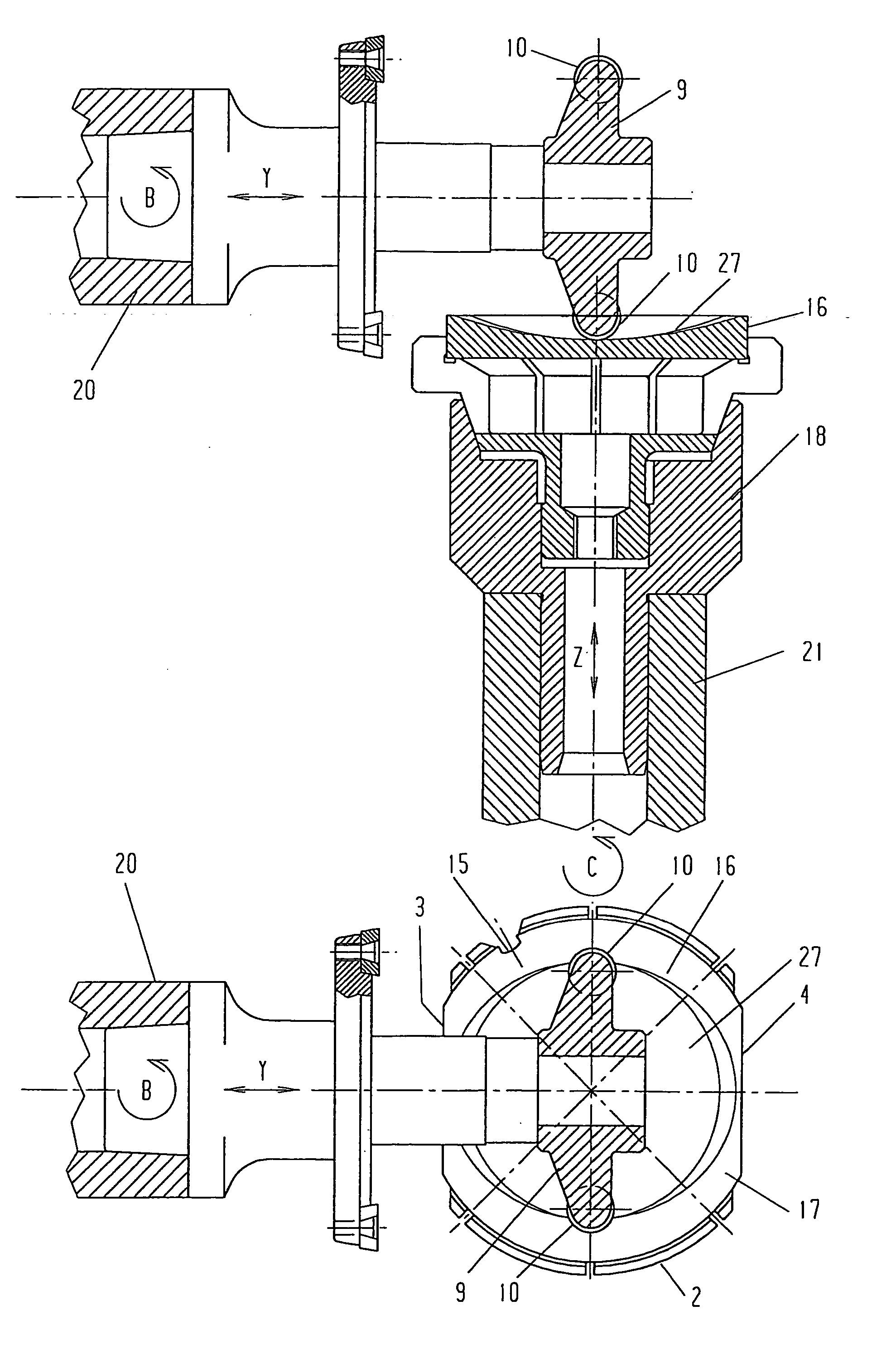
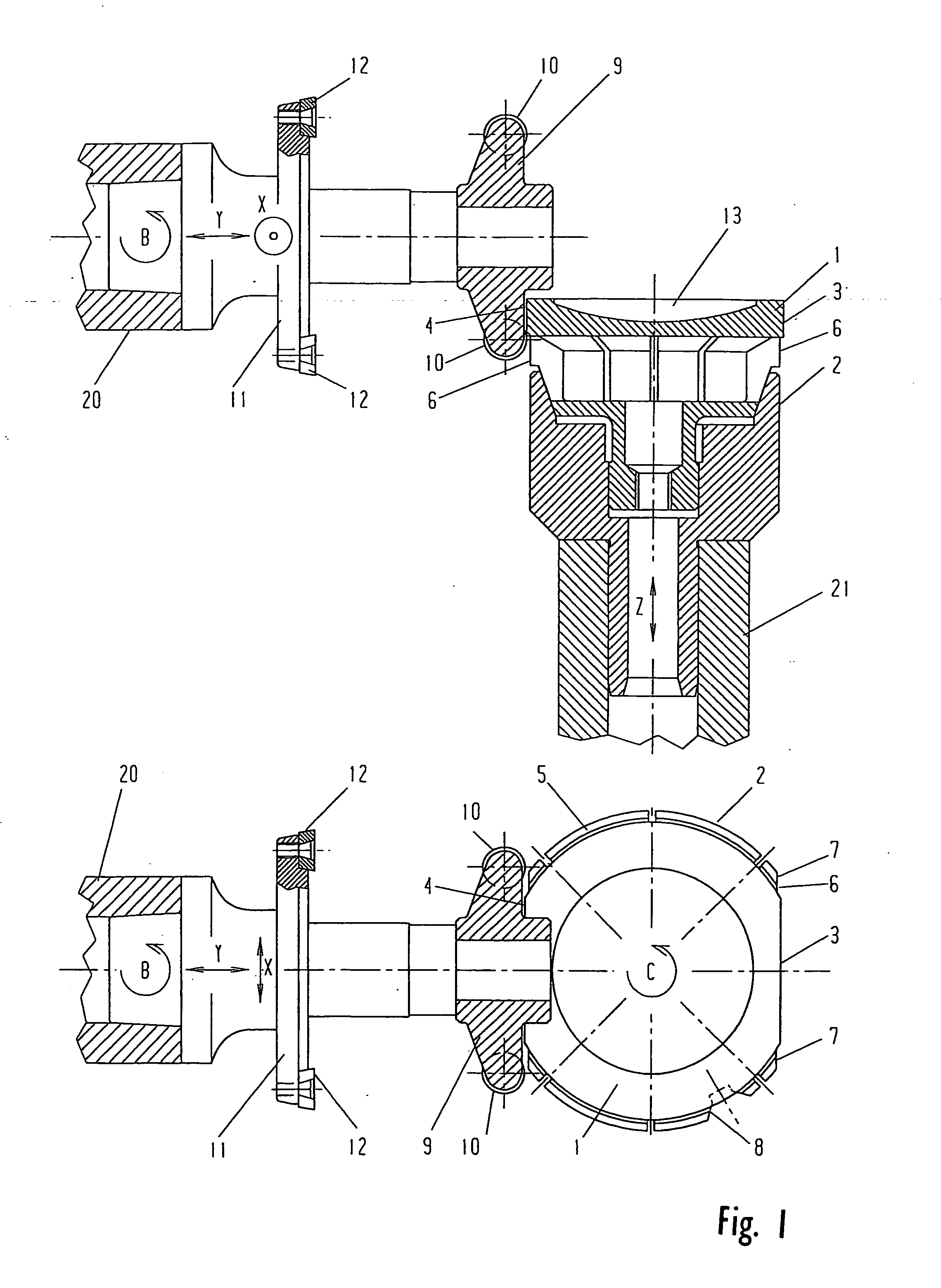
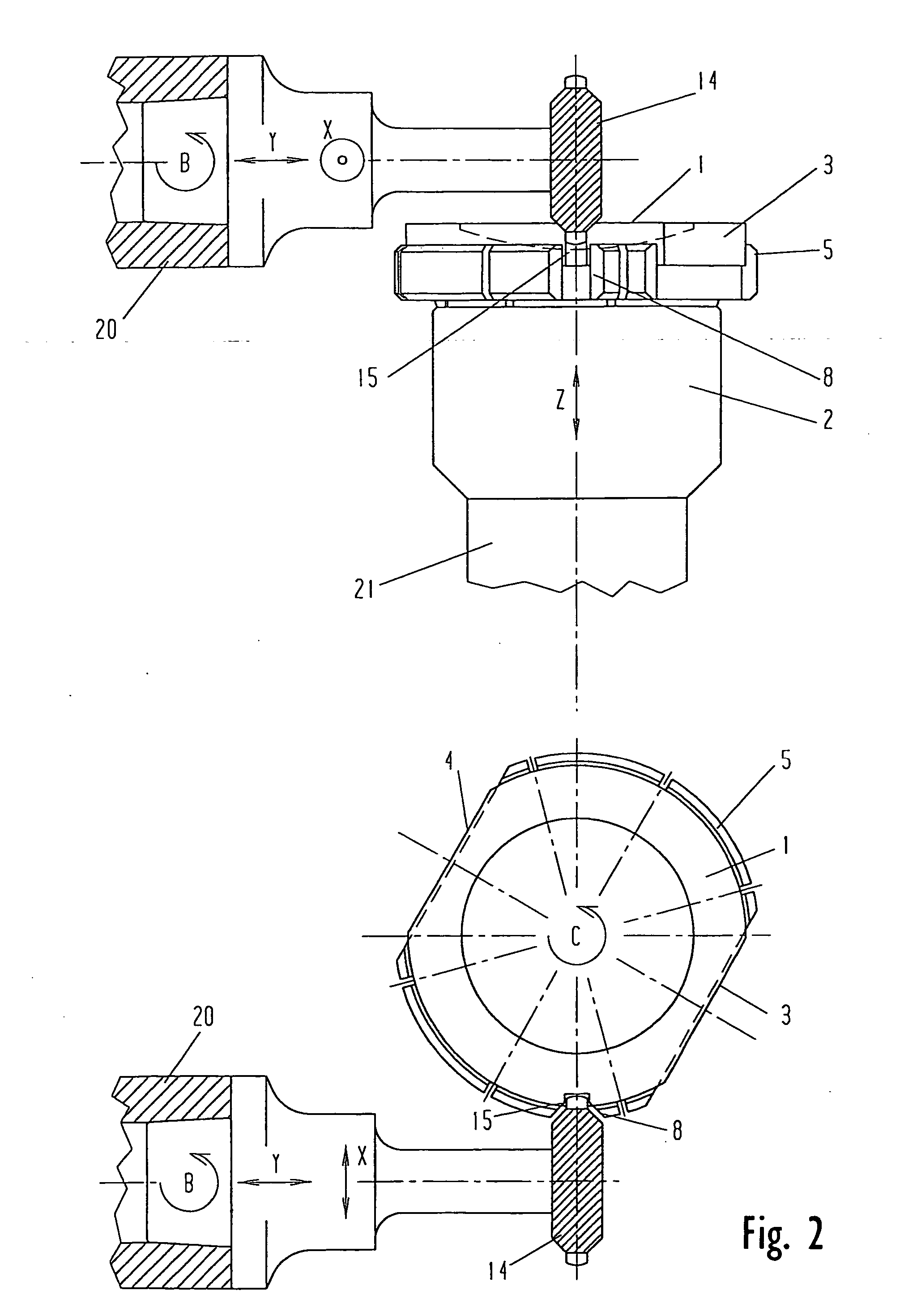
[0212] The illustrations of the devices do not show the machines themselves but only their tool and workpiece spindles with the processing and clamping tools attached to them. This simplification was selected for ease of illustration of details of the devices according to the invention.

[0213]FIG. 1 shows the production of the two flattenings 3 and 4 on the milling / turning machine in a front view and a top view (sectional views).

[0214] The plastic blank 1 is clamped in a clamping tool 2 which is connected with the workpiece spindle 21 of the milling / turning machine.

[0215] In this processing step, th...


PUM

PropertyMeasurementUnit
Thicknessaaaaaaaaaa
Diameteraaaaaaaaaa
Shapeaaaaaaaaaa

Abstract

The invention concerns a method for producing ophthalmic lenses that uses plastic blanks in the form of flat, round discs. The outer edge of said plastic blanks is clamped and the desired final surface geometry and surface quality of the front faces of the lens are subsequently produced by a machining process using grinders and / or lathes and by smoothing and polishing processes. During machining, a thicker annular region is retained on the outer circumference of the workpiece. The annular region clamps or arranges the workpiece during machining and transport operations and stabilizes the lens for additional machining. Shaped pieces for identifying the machining axes are attached to the annular region. The lens is provided with fine markings to characterize the lens that has been produced, with the lens then being separated from the region.

Description

CROSS-REFERENCE TO RELATED APPLICATIONS [0001] This application is a continuation of International Patent Application No. PCT / EP2004 / 002515, filed Mar. 11, 2004. This PCT application was not in English as published under PCT Article 21(2).FIELD OF THE INVENTION [0002] The invention relates to a method and a device for producing ophthalmic lenses and other shaped bodies with optically active surfaces. BACKGROUND OF THE INVENTION [0003] Ophthalmic lenses are generally made of plastics which have a high refractive index while presenting a low specific gravity and a good machinability. However, this method may also be used for producing ophthalmic lenses from silicate glass. Machining is usually done by chip removing processes on millers, lathes, grinders and polishing machines. [0004] To simplify the language, “ophthalmic lenses and other shaped bodies” will hereinafter only be referred to as “ophthalmic lenses”. It is understood, however, that this always also includes other comparabl...

Claims


Application Information

Patent Timeline
IPC IPC(8): B24B1/00B24B13/005B24B13/06B29D11/00
CPCB24B13/0057Y10T29/511B29D11/00932B24B13/06
Inventor MANDLER, ROLANDWEIS, REINHOLD
Owner OPTOTECH OPTIKMASCHEN
Learn More