

Desulfurization and novel sorbent for same
a technology of sorbent and sulfur, applied in the field of sorbent composition, can solve the problems of large hydrogen consumption cost, high sulfur content of such automotive fuels, and reduced octane number, and achieve the effect of minimizing hydrogen consumption and reducing the saturation of olefins and aromatics
- Summary
- Abstract
- Description
- Claims
- Application Information
AI Technical Summary
Benefits of technology
Problems solved by technology
Method used
Image


Examples
example i
[0080] Sorbent A (control) was prepared by mixing 20 grams of sodium pyrophosphate (available from Aldrich Chemical Company, Milwaukee, Wis.) and 2224 grams of distilled water in a Cowles dissolver to create a sodium pyrophosphate solution. A 200 gram quantity of aluminum hydroxide powder (Dispal® Alumina Powder, available from CONDEA Vista Company, Houston, Tex.), a 628 gram quantity of diatomaceous earth (Celite® Filter Cell, available from Manville Sales Corporation, Lampoc, Calif.), and a 788 gram quantity of zinc oxide powder (available from Zinc Corporation, Monaca, Pa.) were then mixed to form a powdered mixture. The powdered mixture was slowly added to the sodium pyrophosphate solution and mixed for 15 minutes to create a sorbent base slurry. The resulting mixed slurry was sieved through a 25-mesh screen.
[0081] The sorbent base slurry was then formed into sorbent base particulate using a counter-current spray drier (Niro Mobile Minor Spray Dryer, available from Niro Inc., C...
example ii
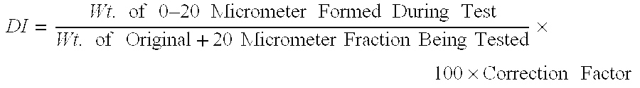
[0095] The attrition resistance of Sorbents A-E was then determined using the Davison Test. The Davison Index, which represents the weight percent of the over 20 micrometer particle size fraction which is reduced to particle sizes of less than 20 micrometers under test conditions, was measured using a Jet cup attrition determination method. The Jet cup attrition determination involved screening a 5 gram sample of sorbent to remove particles in the 0 to 20 micrometer size range. The sorbent particles above 20 micrometers were then subjected to a tangential jet of air at a rate of 21 liters per minute introduced through a 0.0625 orifice fixed at the bottom of a specially designed Jet cup (1″ I.D.×2″ height) for a period of 1 hour. The Davison Index (DI) was calculated as follows: DI=Wt. of 0–20 Micrometer Formed During TestWt. of Original+20 Micrometer Fraction Being Tested×100×Correction Factor
The correction factor of 0.3 was determined using a known calibr...
example iii
[0098] Sorbents C-E were then reactor tested under desulfurization conditions.
[0099] A 10 gram quantity of −100 / +325 mesh Sorbent C was placed in a reactor (1 inch I.D. fluidized bed reactor with clam shell heater) and heated to 700° F. Catalytically Cracked Gasoline (CCG) (345 ppmw sulfur), nitrogen, and hydrogen were then simultaneously charged to the reactor at 13.4 ml / hr, 150 cc / min, and 150 cc / min, respectively. The reactor bed temperature was maintained between about 730° F. and 740° F. Effluent samples were taken at 4 hourly increments and designated Samples 1A-4A.
[0100] CCG flow to the reactor was then terminated and the sulfurized sorbent was regenerated with air (60 cc / min) and nitrogen (240 cc / min) at a temperature of about 900° F. for about 100 minutes. The reactor temperature was then reduced to about 700° F. and the regenerated sorbent was reduced with hydrogen (300 cc / min) for about 95 minutes. CCG (345 ppmw sulfur), nitrogen, and hydrogen were then simultaneously c...
PUM
| Property | Measurement | Unit |
|---|---|---|
| mean particle size | aaaaa | aaaaa |
| temperature | aaaaa | aaaaa |
| temperature | aaaaa | aaaaa |
Abstract
Description
Claims
Application Information