
Discharge gas treatment catalyst and method and apparatus for treating discharge gas

Active Publication Date: 2006-04-20
MITSUBISHI HEAVY IND LTD
View PDF24 Cites 33 Cited by
  • Summary
  • Abstract
  • Description
  • Claims
  • Application Information

AI Technical Summary

Benefits of technology

[0008] The present invention has been made under such circumstances, and an object of the present invention is to provide a discharge gas treatment catalyst which further prevents SO3 formation occurring in catalytic reaction and which effectively decreases NOx and SO3, which co-exists with NOx in a discharge gas and which serves as a source for an S-containing substance such as acidic ammonium sulfate causing lowered catalyst performance and corrosion of an apparatus disposed on the downstream side of a treatment system containing the catalyst. Another object is to provide a discharge gas treatment method employing the catalyst. Still another object of the invention is to provide a discharge gas treatment apparatus employing the catalyst.
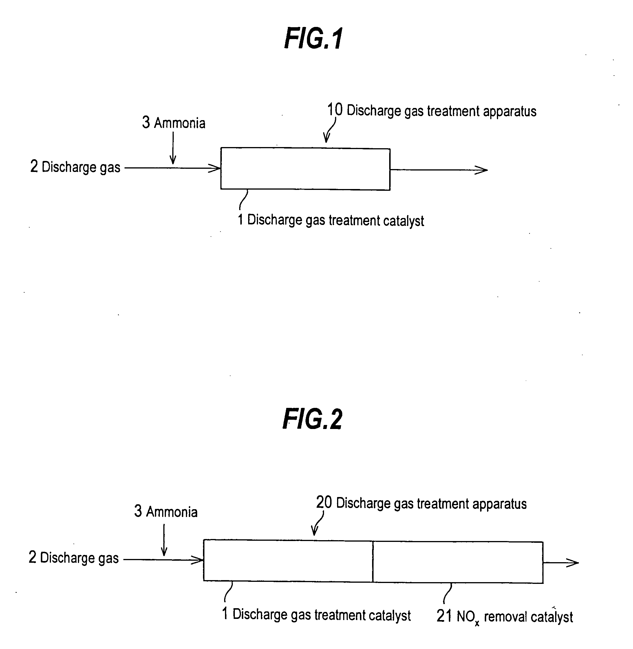
[0019] bringing the discharge gas containing ammonia into contact with the aforementioned discharge gas treatment catalyst, whereby sulfur trioxide and nitrogen oxide are reduced.

Problems solved by technology

The corrosion causes plugging, partial clogging, etc., increasing pressure loss.

Method used


Image

  • Discharge gas treatment catalyst and method and apparatus for treating discharge gas
  • Discharge gas treatment catalyst and method and apparatus for treating discharge gas

Examples


example 1

[0032] A honeycomb-form catalyst (hereinafter referred to simply as honeycomb catalyst) formed of 100 parts by weight of titania (TiO2) and 9 parts of tungsten oxide (WO3) (TiO2—WO3 honeycomb catalyst) was immersed in a ruthenium chloride (RuCl3) solution (Ru concentration: 40 g / L) for one minute. Through impregnation caused by immersion, Ru (1 part) was carried by the titania-tungsten oxide catalyst (100 parts). The concentration of ruthenium chloride solution so that ruthenium (1 part) is carried by a honeycomb substrate (100 parts), when the titania-tungsten oxide honeycomb catalyst has a water content of 0.25 mL per 1 g of the catalyst, is calculated as follows. 0.01×(1 / 0.25)=0.04⁢ ⁢g⁢ / ⁢mL=40⁢ ⁢g⁢ / ⁢L

[0033] Thus, when a honeycomb catalyst (100 parts) is immersed for one minute in a ruthenium chloride (RuCl3) solution having an Ru concentration of 40 g / L, the honeycomb catalyst (100 parts) is impregnated with ruthenium (1 part).

[0034] The titania-tungsten oxide catalyst carrying...

example 2

[0038] The same slurry (No. 1) for catalyst coating as prepared in Catalyst preparation method 1 and the same honeycomb catalyst serving as a substrate as employed in Catalyst preparation method 1 were used. The set of immersion of the substrate in the slurry (No. 1), drying the substrate immersed in the slurry, and firing the dried substrate was performed twice, whereby the slurry (No. 1) was applied to the surface of the substrate at 200 g / m2. The thus-prepared honeycomb catalyst was employed as a discharge gas treatment catalyst (No. 2).

example 3

[0039] A honeycomb catalyst formed of 100 parts of titania (TiO2) and 20 parts of tungsten oxide (WO3) was immersed in a ruthenium chloride (RuCl3) solution. Through impregnation caused by immersion, Ru (1 part) was carried by the titania-tungsten oxide catalyst (100 parts). Subsequently, the titania-tungsten oxide catalyst carrying ruthenium was dried, followed by firing at 500° C. for five hours.

[0040] The thus-formed titania-tungsten oxide-ruthenium honeycomb catalyst was crushed by use of a crusher to a particle size of 10 mm or less. By use of a wet ball mill, the formed powder was further pulverized with water, to thereby prepare a slurry (No. 3) for catalyst coating.

[0041] In a manner similar to that employed in Catalyst preparation method 1, a honeycomb catalyst was produced, to thereby provide a discharge gas treatment catalyst (No. 3).


PUM

PropertyMeasurementUnit
Percent by massaaaaaaaaaa

Abstract

The invention provides a discharge gas treatment catalyst which can effectively decreases NOx and SO3 contained in a discharge gas. The discharge gas treatment catalyst, for removing nitrogen oxide and sulfur trioxide from a discharge gas, includes a carrier which is formed of titania-tungsten oxide and which carries ruthenium, and a titania-tungsten oxide-based NOx removal catalyst serving as a substrate which is coated with the carrier. When a discharge gas to which ammonia has been added and which contains SO3 and NOx is brought into contact with the catalyst, decomposition of ammonia is suppressed by ruthenium, and reduction of SO3 and NOx contained in the discharge gas is promoted, whereby SO3 concentration and NOx concentration can be further decreased.

Description

BACKGROUND OF THE INVENTION [0001] 1. Field of the Invention [0002] The present invention relates to a discharge gas treatment catalyst for use in removal of nitrogen oxide (NOx) and sulfur trioxide (SO3) from a gas discharged by a boiler or a similar apparatus. The invention also relates to a method and apparatus for treating a discharge gas in the presence of the catalyst (hereinafter may be referred to as a discharge gas treatment method and a discharge gas treatment apparatus). [0003] 2. Background Art [0004] In order to remove nitrogen oxide (NOx) from contained in a discharge gas produced from a boiler, a gas turbine, a combustion furnace, etc., in practice, there has currently been employed an ammonia catalytic reduction method in which NOx is decomposed by use of ammonia (NH3), serving as a reducing agent, in the presence of a nitrogen oxide removal catalyst (hereinafter abbreviated as “an NOx removal catalyst”), to thereby form nontoxic nitrogen and water. [0005] In many ca...

Claims


Application Information

Patent Timeline
IPC IPC(8): B01D53/56
CPCB01D53/79B01D53/8609B01D53/8628
Inventor OBAYASHI, YOSHIAKIONISHI, TOSHIYUKIIIDA, KOZO
Owner MITSUBISHI HEAVY IND LTD
Learn More