Surface modification process

Inactive Publication Date: 2006-04-20
BREWIS DEREK +2
View PDF2 Cites 17 Cited by
  • Summary
  • Abstract
  • Description
  • Claims
  • Application Information

AI Technical Summary

Benefits of technology

[0028] In some aspects of the present method, the modification step itself may be carried out at an elevated temperature. This may be useful in decreasing the reaction time required for the modification step and ensuring that the modification reaction is as efficient as possible, requiring the minimum quantity of silane for achieving suitable levels of modification. The degree of heating employed is not strictly limited, and is dependent on the method of modification, the type of surface, and the particular silane compound employed. The heating may include heating the surface, or heating the silane, or heating both. When a solvent is employed, the solution of silane and solvent may be heated. In a preferred embodiment, when the method of modification employed involves immersion, the modification step is carried out by heating the silane solution to the desired temperature, and immersing the unheated surface in the solution. Typically, the modification step is carried out at a temperature of 10-200° C. More preferably, the modification step is carried out at from ambient temperature to 100° C., such as from 15-100° C., from 20-100° C. or from 25-100° C. When the surface to be modified is a plastic surface, it is preferred that the modification step is carried out at no more than 80° C.
[0029] When the surface to be modified is formed from a plastics material or a polymeric material, such as PBT or acetal, it is preferred in some embodiments of the invention to coat the plastics surface with aluminium before in turn modifying the aluminium surface. Aluminium can be deposited onto plastics materials using a sputter coating method, (e.g. with an Edwards S105H DC sputter coater). An aluminium layer a few nanometres thick can be deposited in this way. Such thicknesses are sufficient for the purposes of the present invention.
[0030] The fluorine-containing silane compound is not especially limited, provided that it is capable of modifying the surface to reduce the affinity of the surface to substances, such as pharmaceuticals, which may come into contact with it. Generally, the fluorine-containing silane compound comprises at least one fluorine-containing group which has a fluorinated region at some position within the group. Preferably, the group has a fluorinated terminus. By fluorinated, it is meant partial or complete substitution of a region of the group with fluorine atoms. By terminus

Problems solved by technology

Adsorption of drugs onto the internal surfaces of aluminium cans, and onto the polymers and metals utilised in valve construction, can be a problem in the development of pressurised metered dose inhaler (pMDI) products.
However, there are problems with known approaches.
In order to justify the addition of a drug overage it must be shown that adsorbed drug cannot be displaced from the device componentry, and therefore present a risk of overdosing, whereas the addition of a polymer coating to an a

Method used


Image

  • Surface modification process
  • Surface modification process
  • Surface modification process

Examples


example 1

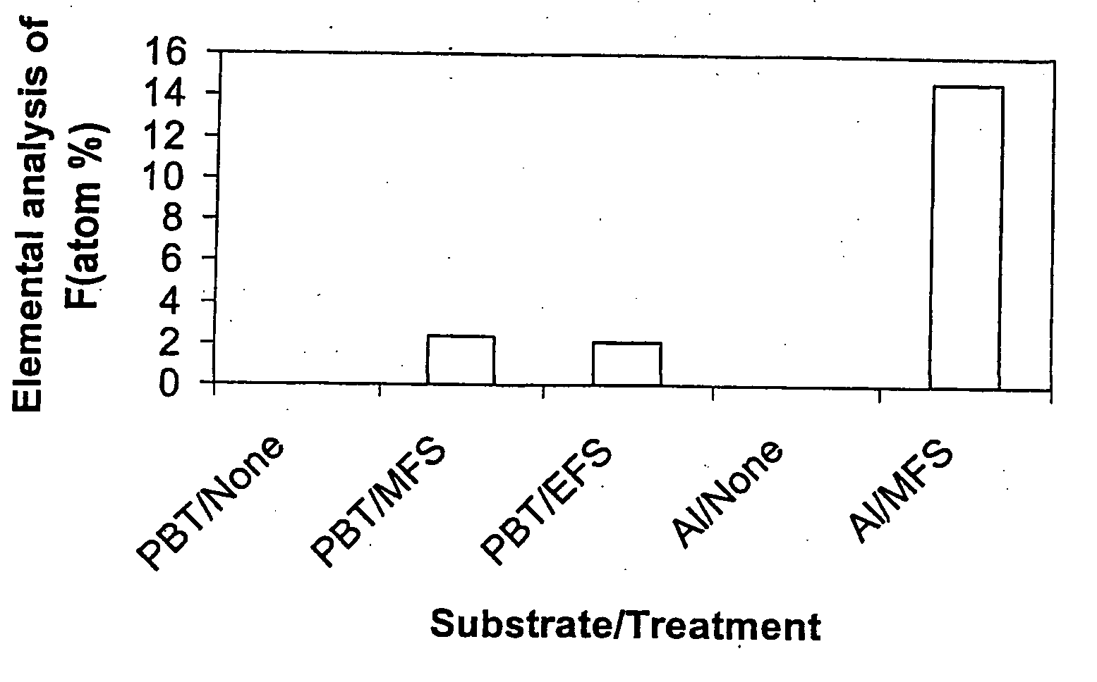
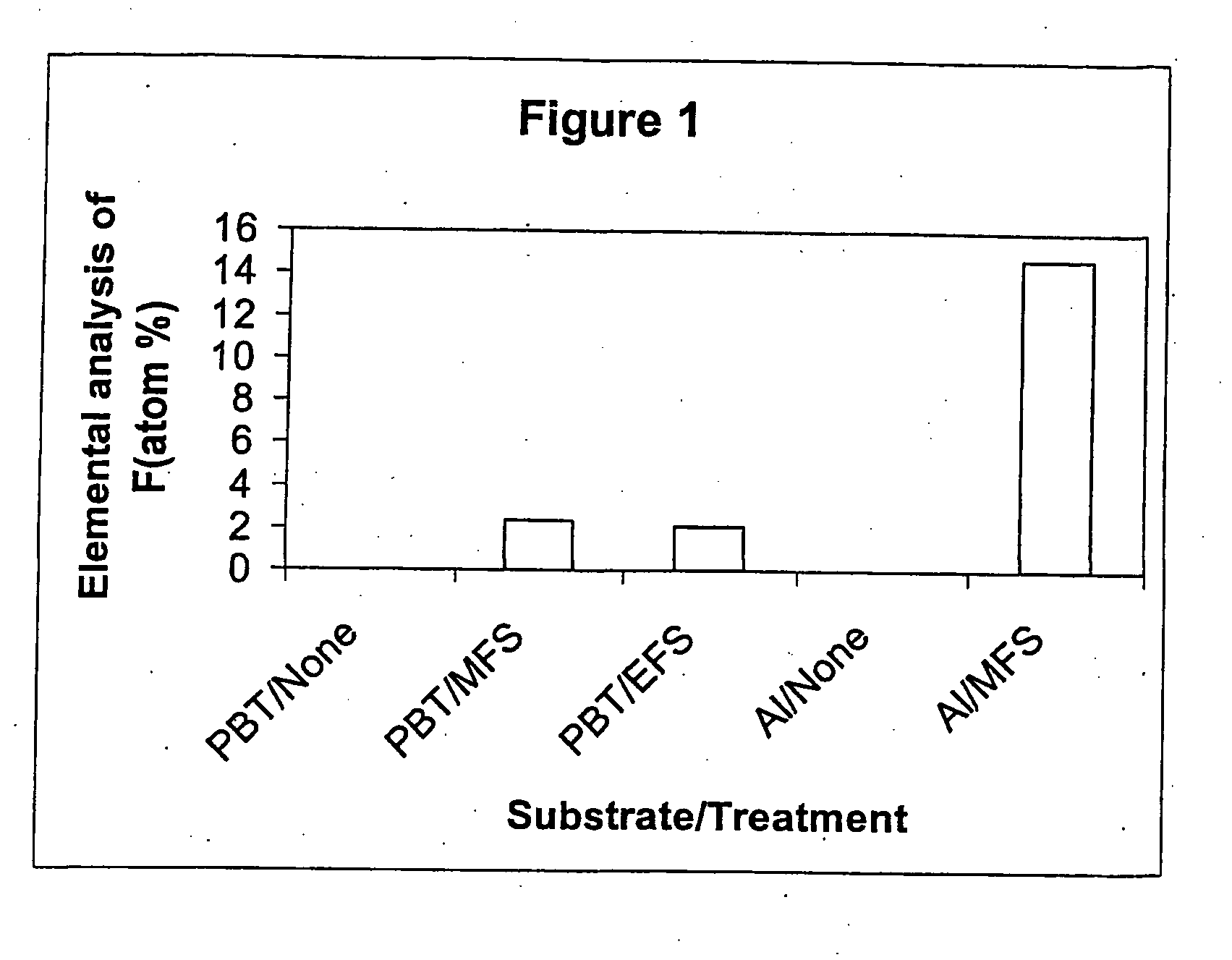
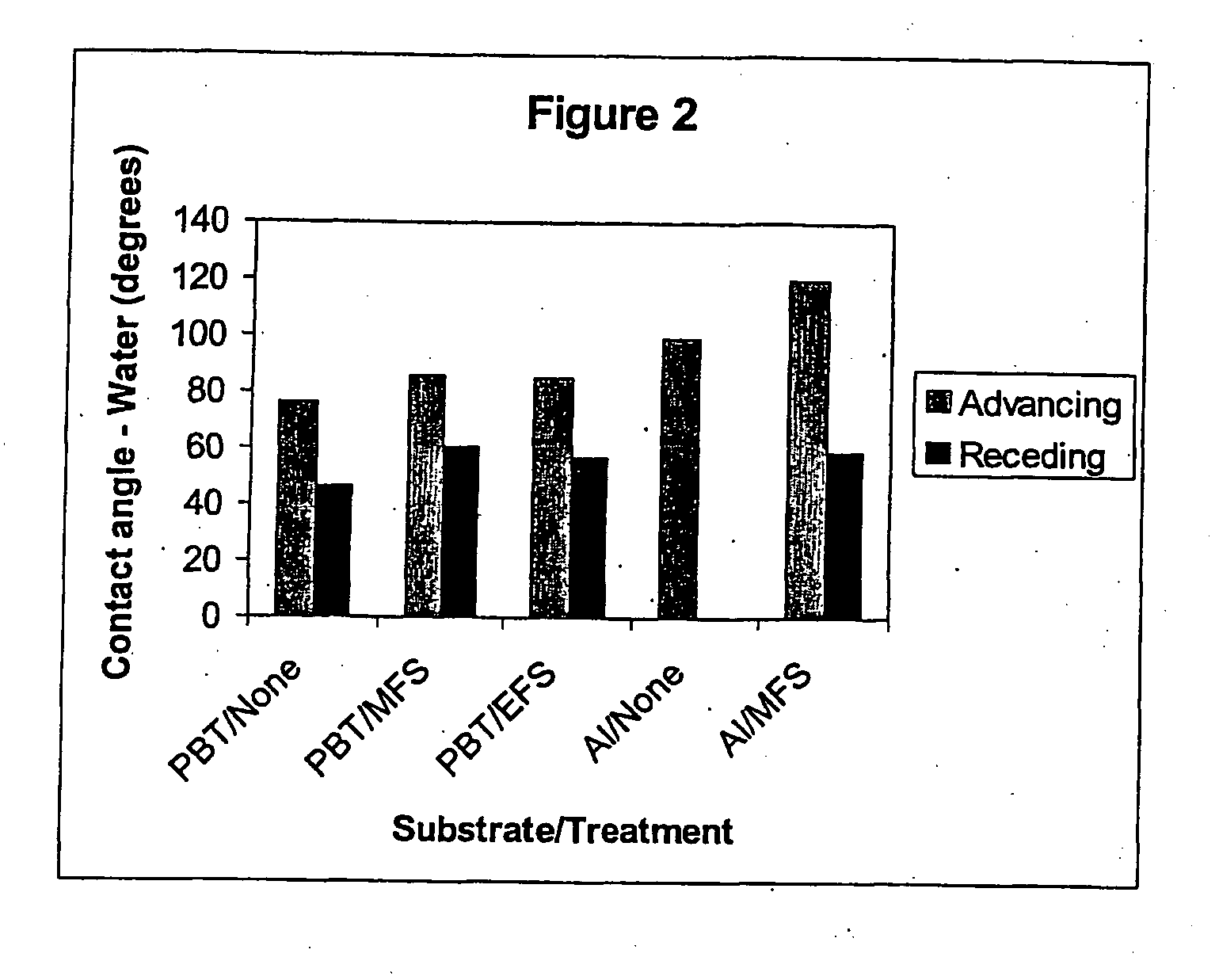
[0092] This Example intends to demonstrate the effect of modifying metal and plastics surfaces with fluorine-containing silanes. Sheets of aluminium and polybutylene terephthalate (PBT) were decontaminated by ultrasonic agitation in 1,1,2-trichloro-1,2,2-trifluoroethane (Freon® 113). Silane solutions were prepared by dissolving 0.5 g of fluoroalkyl silane in 1 ml of Freon® 113. The silane moieties used for surface modification were 1H,1H,2H,2H-perfluoroooctyltrimethoxysilane (MWS) and 1H,1H,2H,2H-perfluorooctyltriethoxysilane (EFS). The Freon® 113 solution was diluted with 94 ml methanol, followed by 5 ml 1M acetic acid. The substrate was immersed in the solution for 5 min, after which it was removed at a rate of 0.5 mm / min. The polymers and aluminium were then heated for 10 min at 120° C. and 130° C. respectively, washed with Freon® 113 for 5 mins with ultrasonic agitation to remove unreacted silane, and allowed to air dry. A fresh fluoroalkyl silane solution was prepared for each ...

example 2

[0095] This Example is intended to demonstrate optimised conditions for the surface modification of aluminium. 30×10×0.47 mm aluminium strips were treated with the silane formulations detailed in Table 2, utilising the process described in Example 1.

TABLE 2FormulationsComponentsABCDMFS (g)0.50.250.250.25Freon ® 113 (ml)1.00.50.50.5Methanol (ml)94.094.01 M acetic acid (ml)5.0Deionised water (ml)6.0900.1 M hydrochloric acid (ml)10Toluene (ml)100

[0096] Surfaces were characterised by XPS and contact angle measurement with water. Results are shown in FIGS. 3 and 4.

[0097]FIGS. 3 and 4 indicate that a high drying temperature and the presence of 0.01 M hydrochloric acid to bring about acid hydrolysis of the fluoroalkyl silane and to activate the aluminium surface (Formulation C, as described in Table 2), produces the highest contact angle values and elemental F content.

example 3

[0098] This Example aims to demonstrate the advantages of modifying the surface of an aluminium pMDI can. Rectangles (20×10 mm) were partially cut from the walls of 19 ml cans (Presspart, UK), leaving a bridge in place. These cans were decontaminated, together with additional intact cans, by ultrasonic agitation in Freon® 113. After drying, a sample can was taken as a control, and the remaining cans were submerged in Formulation C for 30 min. The cans were then removed, dried at room temperature, and then placed in an oven at 130° C. for 10 min. They were then immersed in Freon® 113 for 5 min with ultrasonic agitation, and the partially cut rectangles removed for surface analysis by XPS (using an ESCALAB 5 device) and Auger Electron Spectroscopy (AES) (using a Varian Scanning Auger electron spectrometer).

[0099]FIG. 5 indicates that pMDI cans were successfully treated with Formulation C, with both XPS and AES data indicating higher levels of F in treated cans compared to controls. A...


PUM

PropertyMeasurementUnit
Temperatureaaaaaaaaaa
Volumeaaaaaaaaaa

Abstract

Provided is a method for modifying an internal surface of a container or closure, which method comprises contacting the internal surface with a fluorine-containing silane conpound to form a modified surface, wherein the container is suitable for storing a medicament.

Description

FIELD OF THE INVENTION [0001] The present invention relates to a process for modifying an inside surface of a container and / or a closure and to a container and / or closure modified according to the process of the present invention. In particular, the present invention relates to a process for modifying an inner surface of a canister used for storing a medicament to prevent the medicament from adhering to the canister. Generally the container, closure or canister is one comprising a cap and a metering unit comprising a valve, for delivery of the medicament BACKGROUND OF THE INVENTION [0002] Adsorption of drugs onto the internal surfaces of aluminium cans, and onto the polymers and metals utilised in valve construction, can be a problem in the development of pressurised metered dose inhaler (pMDI) products. It is known that this adsorption, and consequent reduction in emitted dose, may be to a degree countered by approaches such as the addition of fluorocarbon polymer coating to the in...

Claims


Application Information

Patent Timeline
IPC IPC(8): B32B27/08B65D25/14A61J1/00A61J1/05A61K9/72A61M15/00B05D1/18B05D5/08B05D7/22B05D7/24C08J7/06C08J7/12C23C16/30C23C16/42C23C22/02
CPCA61M15/009A61M2205/0222B05D1/18B05D5/083Y10T428/1352C08J7/065C08J7/12C23C22/02C23C2222/20B65D83/75
Inventor BREWIS, DEREKBURNS, STEVECOLTHORPE, PAUL
Owner BREWIS DEREK
Why Eureka
Try Eureka