Solid state lighting device with improved thermal management, improved power management, adjustable intensity, and interchangable lenses

a solid-state lighting and power management technology, applied in semiconductor devices, point-like light sources, lighting and heating apparatus, etc., can solve the problems of inability to successfully or economically use light emitting diodes and other semiconductor light sources to illuminate physical spaces, inability to adjust the light emission pattern, and inability to meet the needs of lighting and heating, etc., to achieve easy mass production and efficient use, easy to adjust the light emission pattern, and low cost

Inactive Publication Date: 2006-05-11
NXGEN TECH
View PDF25 Cites 198 Cited by
  • Summary
  • Abstract
  • Description
  • Claims
  • Application Information

AI Technical Summary

Benefits of technology

[0008] It is an object of this invention to obviate the above-mentioned drawbacks and limitations in the prior art. This invention more particularly aims at providing a solid state lighting device (LED lamps) which can be easily mass produced efficiently and at minimum cost, has an easily adjustable light emission pattern, is electrica

Problems solved by technology

In the prior art, light emitting diodes (LED's) and other semiconductor light sources have not been successfully or economically used to illuminate physical spaces.
In addition, these designs are severely limited due to spatial considerations as the arrangement of the discreet LED arrays required a great deal of physical space.
However, the thermal designs are inadequate, impractical, or both.
Most designs call fo

Method used


Image

  • Solid state lighting device with improved thermal management, improved power management, adjustable intensity, and interchangable lenses
  • Solid state lighting device with improved thermal management, improved power management, adjustable intensity, and interchangable lenses
  • Solid state lighting device with improved thermal management, improved power management, adjustable intensity, and interchangable lenses

Examples


Embodiment Construction

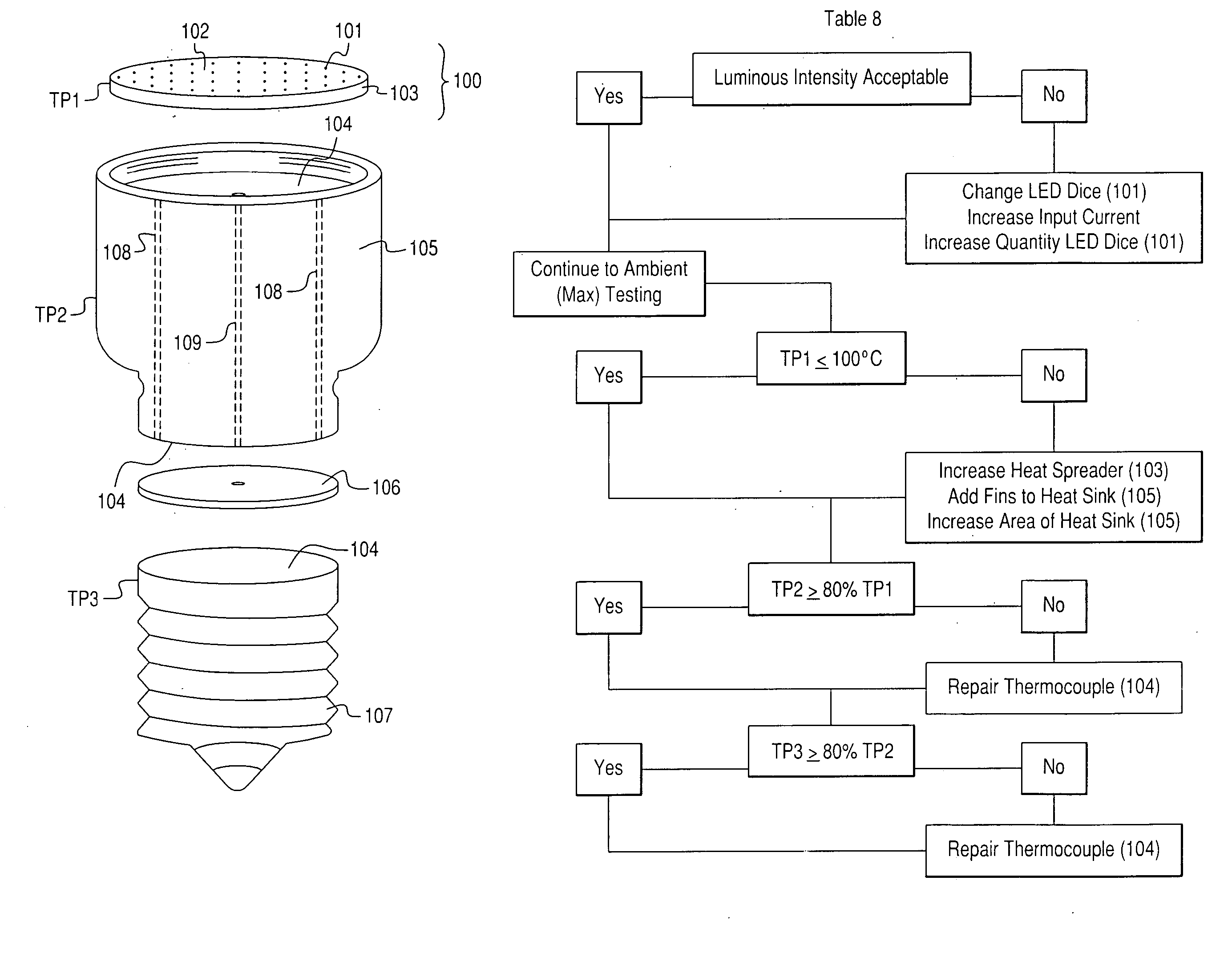
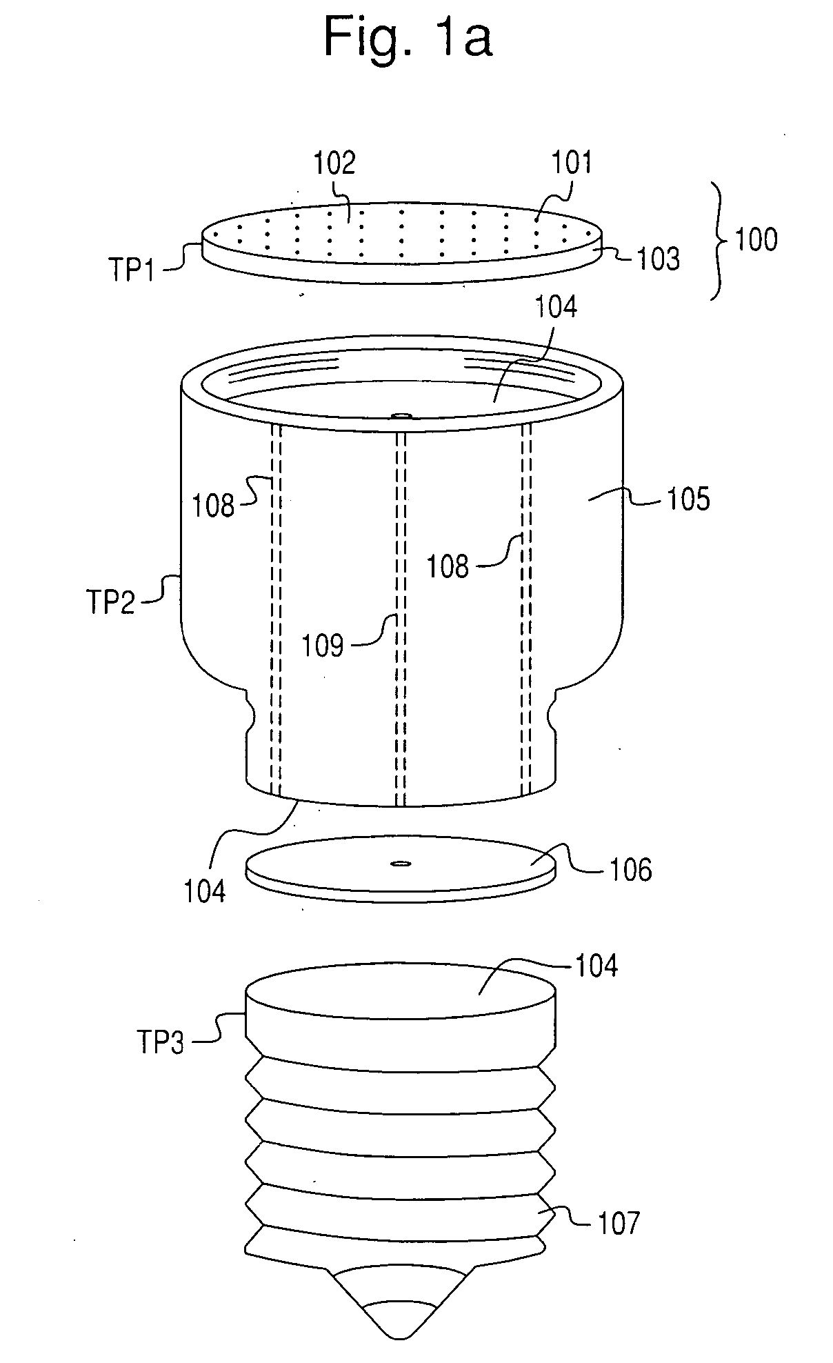
[0027] As illustrated in FIGS. 1a, 2a, 3a, and 5 the lighting module (100), containing the LED chips (101), affixed directly to the PCB (102) using conventional chip-on-board methods as known in the art. The PQB (102) is bonded directly to a backer plate / heat spreader (103) manufactured from aluminum, copper, ceramic, or other material with superior heat transfer properties.

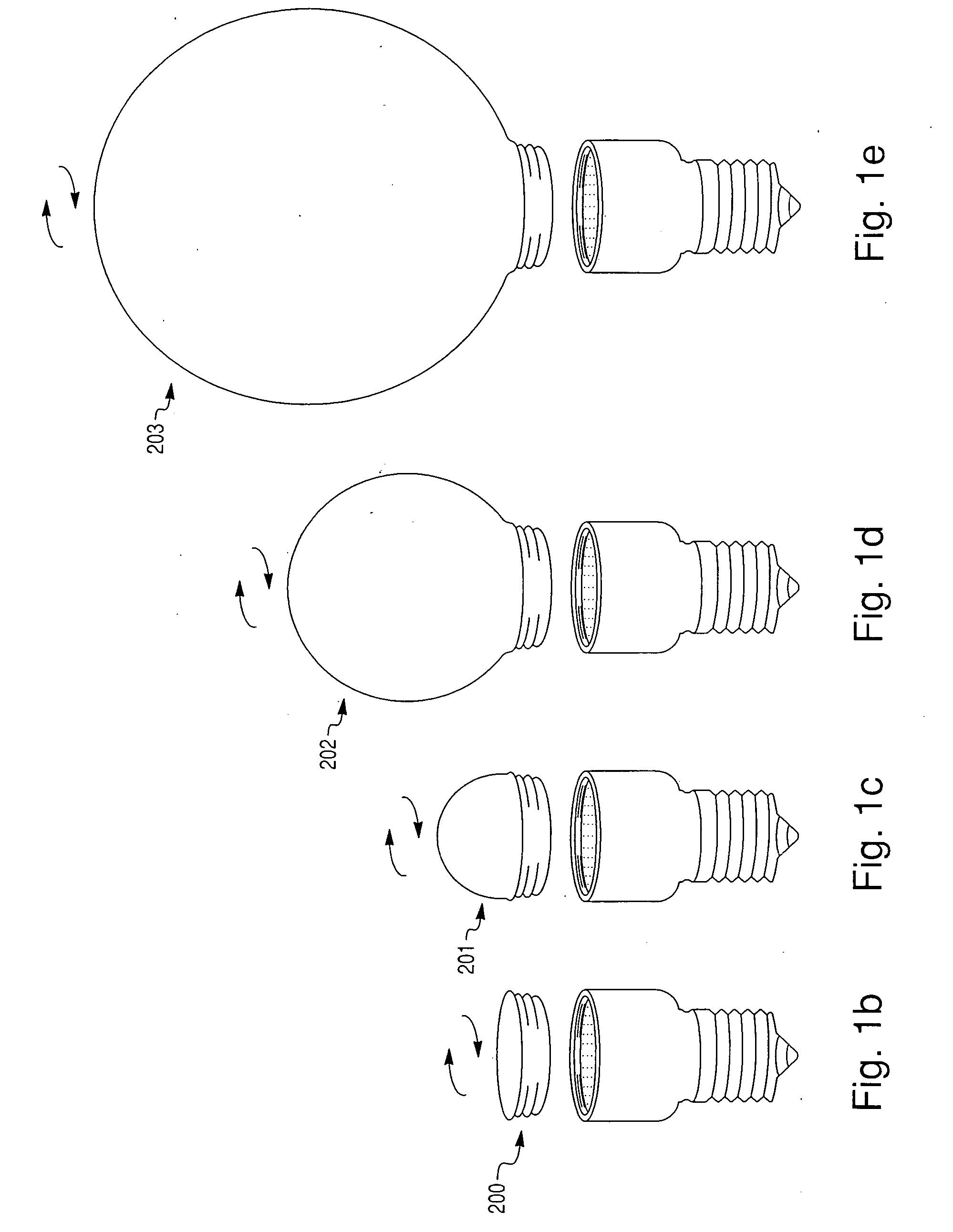
[0028] It should be noted that the total surface area of lighting module (100), in particular backer plate / heat spreader (103) can be made smaller or larger as well as thicker to match the thermal requirements associated with the LED chip (101) density and quantity as well as the modules total power requirement in Watts. It should be further noted that the light emission module (100) can be manufactured using multiple planar surfaces that are coupled electrically. Test samples manufactured using a circular, single plane light emission module exhibited uniform light distribution when a diffusing globe was affixed...


PUM


Abstract

A solid state (light emitting diode) lamp in numerous configurations have improved thermal management by providing a direct thermal pathway from the plurality of LED chips to the threaded screw base (standard 100˜240 VAC lamp socket), or power coupling. The control circuitry is disposed opposite the printed circuit board and LED chips with respect to the heat sink so that the heat sink is interposed between the printed circuit board and the control circuitry. The LED chips are powered using a high voltage/high current configuration. The light radiation pattern is infinitely adjustable (very wide through very narrow) via a system of easily interchangeable lenses. The solid state lamps can be mass produced rapidly at significantly lower cost with very high luminous intensity. ESD protection may be included to protect the LED chips from electrostatic discharge damage.

Description

[0001] This application is a Non-Provisional Patent Application of U.S. Provisional Patent Application No. 60 / 625,163 filed Nov. 5, 2004, which is hereby incorporated by reference.BACKGROUND OF THE INVENTION [0002] 1. Field of Invention [0003] The present invention relates to light emitting diode lamps, and more particularly to light emitting diode lamps that can be easily mass produced, have adjustable integrated thermal management systems located outside the enclosing globe or lens, have maximum thermal transfer area between components, are designed to operate at high voltage (100˜240 VAC), are designed to operate at high current, thus higher total power (W), and are capable of high luminous intensity, and have a light beam radiation pattern that is infinitely adjustable. [0004] 2. Description of the Prior Art [0005] In the prior art, light emitting diodes (LED's) and other semiconductor light sources have not been successfully or economically used to illuminate physical spaces. E...

Claims


Application Information

Patent Timeline
IPC IPC(8): F21V29/00
CPCF21V3/00F21Y2101/02F21K9/13F21K9/135F21V29/74F21V17/002F21V17/12F21V23/006F21V3/02F21K9/23F21K9/232F21K9/238F21Y2115/10H01L2224/48091H01L2224/73265H01L2924/00014
Inventor ALLEN, DAVID
Owner NXGEN TECH
Why Eureka
Try Eureka