
Negative electrode for lithium ion secondary battery, production method thereof and lithium ion secondary battery comprising the same

Active Publication Date: 2006-05-11
PANASONIC CORP
View PDF3 Cites 101 Cited by
  • Summary
  • Abstract
  • Description
  • Claims
  • Application Information

AI Technical Summary

Benefits of technology

[0021] When a surface of the active material layer which is not in contact with the current collector contacts air, an oxide film is formed on that surface. In so

Problems solved by technology

Graphite materials, however, have a small capacity per unit weight of 372 mAh / g, and a further increase in capacity cannot be expected.
A large volume change of active material results in cracking of active material particles, insufficient contact between active material and current collector, etc, which shortens charge / discharge cycle life.
The formation of such film increases the interface resistance between the active material and the non-aqueous electrolyte, which is considered as a major cause for short charge / discharge cycle life.
However, the above-mentioned prior art references suffer from various problems.
In a silicon thin film, in particular, a large concentration gradient of lithium is produced in the thickness direction, and the capacity easily decreases.
Further, because silicon has an extremely large expansion coefficient, an electrode composed of silicon is highly deformed so that the electrode group is buckled, degrading the battery's characteristics and safety.
Moreover, the production of the negative electrode disclosed by Japanese Laid-Open Patent Publication No. 2002-83594 involves considerable costs because, in order to relieve the expansion stress at the interface between silicon and current collector, it requires the steps of forming the silicon into a columnar structure as well as performing heat treatment for diffusing copper in the silicon.
Summing up, the negative electrode of Japanese Patent Publication No. 2997741 fails to take advantage of the characteristics of high-capacity silicon and to provide a capacity as expected.
A further problem arises when the negative electrode contains graphite as a conductive material: an electrolyte containing propylene carbonate cannot be used, because a film made of decomposed product of propylene carbonate is formed on the surface of the active material.
As for the negative electrode disclosed by Japanese Laid-Open Patent Publication No. 2004-047404, because SiOx is heat-treated to prepare silicon microcrystallites, it is difficult to control the size of the microcrystallites.
Besides, such microcrystallites might crack during the expansion if the microcrystallites grow larger than a certain size.
Also, because the silicon oxide is covered with graphite, an electrolyte containing propylene carbonate cannot be used as is the case in Japanese Patent Publication No. 2997741.
In this case, because the active material particles and the current collector are bonded by the binder, the following problem arises: due to the large volume change of the active material during charge / discharge cycles as stated earlier, the conductive material and the binder cannot adjust to the volume change so that during repeated charge / discharge cycles, the contact between the active material and the conductive material as well as that between the active material and the binder cannot be maintained.
As a result, the contact between the active material and the current collector is weakened, and the polarization increases, decreasing the charge / discharge capacity.
Conversely, when the silicon oxide has a low oxygen ratio, although the charge / discharge capacity is large, the expansion coefficient during charge is large, and the lithium ion conductivity is low.
Moreover, because the silicon oxide thin-film layer is in contact with a carbon layer, the carbon layer and the silicon oxide thin-film layer are separated from each other due to expansion stress during charge, resulting in low current collecting efficiency.
Further, since the production of the carbon layer and the silicon oxide layer requires a completely different production process, the costs for producing negative electrodes will be very high, and negative electrodes cannot be produced efficiently.

Method used


Image

  • Negative electrode for lithium ion secondary battery, production method thereof and lithium ion secondary battery comprising the same
  • Negative electrode for lithium ion secondary battery, production method thereof and lithium ion secondary battery comprising the same
  • Negative electrode for lithium ion secondary battery, production method thereof and lithium ion secondary battery comprising the same

Examples


example 1

Battery 1

(i) Production of Positive Electrode

[0095] With 100 parts by weight of lithium cobalt oxide (LiCoO2) having an average particle size of 5 μm was mixed 3 parts by weigh of acetylene black as a conductive material to prepare a mixture. The obtained mixture was mixed with a N-methyl-2-pyrrolidone (NMP) solution of polyvinylidene fluoride (PVdF) as a binder such that 4 parts by weight of PVDF was added to the mixture, followed by kneading to prepare a positive electrode material mixture paste. The obtained positive electrode material mixture paste was applied onto both surfaces of a current collector sheet made of an aluminum foil, followed by drying to produce an electrode plate. The electrode plate was rolled to have a predetermined thickness to produce a positive electrode.

(ii) Production of Negative Electrode

[0096] The process for producing a negative electrode will be described later below.

(iii) Production of Battery

[0097] A 17500-type cylindrical battery as shown...

example 2

[0136] In this example, comparisons were made between batteries having a propylene-carbonate(PC)-containing electrolyte and batteries having a non-PC-containing electrolyte in terms of discharge capacity ratio at −10° C., initial capacity and charge / discharge efficiency.

Batteries 2 and 3

[0137] Two different electrolytes were prepared: an electrolyte prepared by dissolving LiPF6 in a solvent mixture of EC and dimethyl carbonate (DMC) at a volume ratio of 1:3 at a LiPF6 concentration of 1 mol / L; and another electrolyte prepared by dissolving LiPF6 in a solvent mixture of PC and DMC at a volume ratio of 1:3 at a LiPF6 concentration of 1 mol / L.

[0138] Batteries 2 and 3 were produced in the same manner as the battery 1 was produced except that the above two electrolytes were used. The battery 2 included the electrolyte containing the solvent mixture of PC and DMC. The battery 3 included the electrolyte containing the solvent mixture of EC and DMC.

Comparative Batteries 3 and 4

[0139] F...

example 3

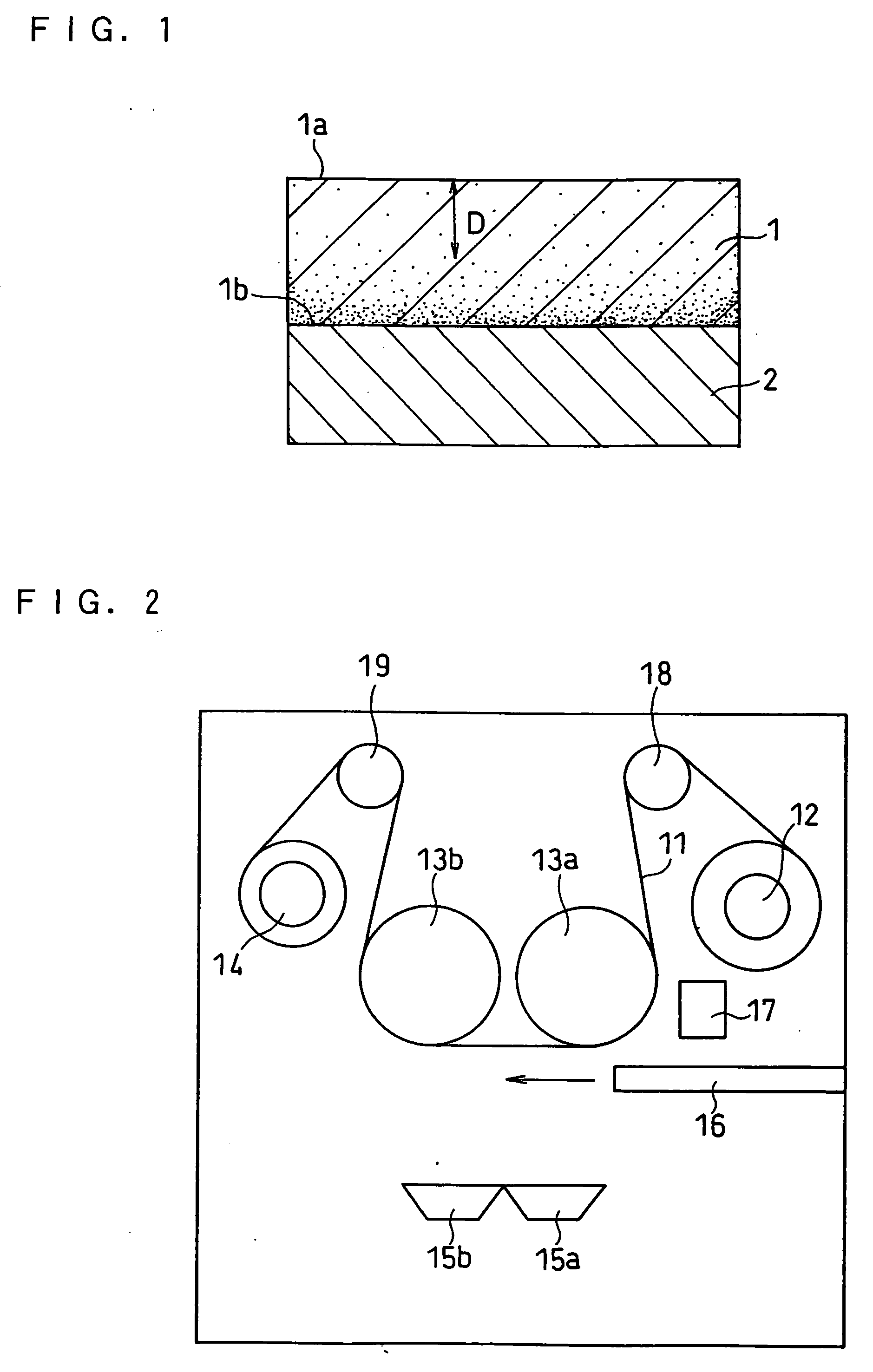
[0163] In this example, the oxygen ratio in the active material layer was changed by changing the flow rate of oxygen introduced in the vacuum chamber of the vapor deposition equipment shown in FIG. 2.

Batteries 4 and 5

[0164] Batteries were produced in the same manner as the battery 1 was produced except that, in the production of the negative electrode, the flow rate of oxygen gas was set at 60 sccm or 100 sccm. The produced batteries were denoted as batteries 4 and 5, respectively.

Battery 6

[0165] A battery was produced in the same manner as the battery 1 was produced except that, in the production of the negative electrode, the flow rate of oxygen gas was set at 100 sccm, that the emission of electron beam was set at 450 mA and that the copper foil was moved at a rate of 40 cm / min. The produced battery was denoted as battery 6.

Batteries 7 to 11

[0166] Batteries were produced in the same manner as the battery 1 was produced except that, in the production of the negative electro...


PUM


Abstract

A negative electrode for a lithium ion secondary battery of the present invention includes a current collector and an active material layer carried on the current collector. The active material layer contains silicon and oxygen. In the thickness direction of the active material layer, an oxygen ratio of the active material is greater at the side of the active material layer in contact with the current collector than at the side of the active material layer not in contact with the current collector. The active material layer contains no binder. By using the negative electrode described above, it is possible to provide a high capacity lithium ion secondary battery having superior high rate charge / discharge characteristics and excellent cycle characteristics.

Description

FIELD OF THE INVENTION [0001] The present invention relates to a lithium ion secondary battery, and more particularly to a negative electrode therefor and a method for producing the negative electrode. BACKGROUND OF THE INVENTION [0002] Attention has been given to lithium ion secondary batteries as a power source for driving electronic equipment. Negative electrodes for lithium ion secondary batteries comprising a graphite material have an average potential during the desorption of lithium ions of about 0.2 V (vs. Li / Li+) and exhibit a relatively flat potential. This potential is lower than that of negative electrodes comprising hard carbon, and therefore equipment that requires high voltage and voltage flatness currently employs, as the power source, lithium ion secondary batteries comprising negative electrodes including a graphite material. Graphite materials, however, have a small capacity per unit weight of 372 mAh / g, and a further increase in capacity cannot be expected. [0003...

Claims


Application Information

Patent Timeline
IPC IPC(8): H01M4/58B05D5/12H01M4/131H01M4/1391H01M4/48H01M4/485H01M4/52H01M4/525
CPCH01M4/0419H01M4/0421H01M4/131H01M4/1391H01M4/485H01M4/525H01M2004/021H01M2004/027Y02E60/122Y02E60/10H01M4/13H01M4/139H01M10/0587
Inventor KOGETSU, YASUTAKAHONDA, KAZUYOSHISATO, TOSHITADAYOSHIZAWA, HIROSHI
Owner PANASONIC CORP
Features
  • Generate Ideas
  • Intellectual Property
  • Life Sciences
  • Materials
  • Tech Scout
  • Unparalleled Data Quality
  • Higher Quality Content
  • 60% Fewer Hallucinations
Learn More