Apparatus and method for coal gasification

Inactive Publication Date: 2006-05-18
COGAS LLC
View PDF15 Cites 29 Cited by
  • Summary
  • Abstract
  • Description
  • Claims
  • Application Information

AI Technical Summary

Benefits of technology

[0005] Accordingly, a process for converting coal into a substitute natural gas begins by placing a charge of coal into a coal gasification unit and causing gasification of at least a portion of the charge by exposing the charge to a gasifying agent and heat. Primary raw gas is recovered at an outlet of the coal ga

Problems solved by technology

Disposition of this by-product presents sign

Method used


Image

  • Apparatus and method for coal gasification
  • Apparatus and method for coal gasification
  • Apparatus and method for coal gasification

Examples


example

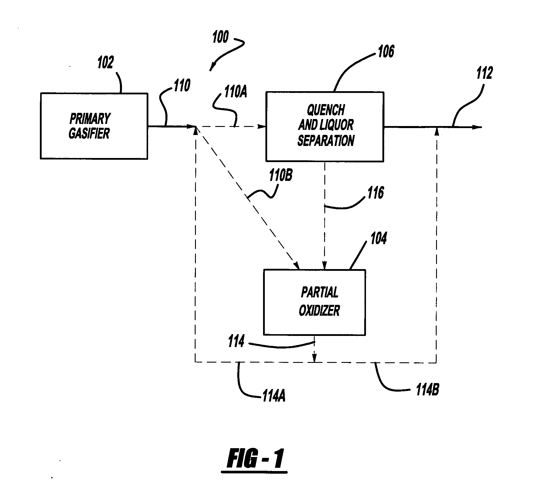
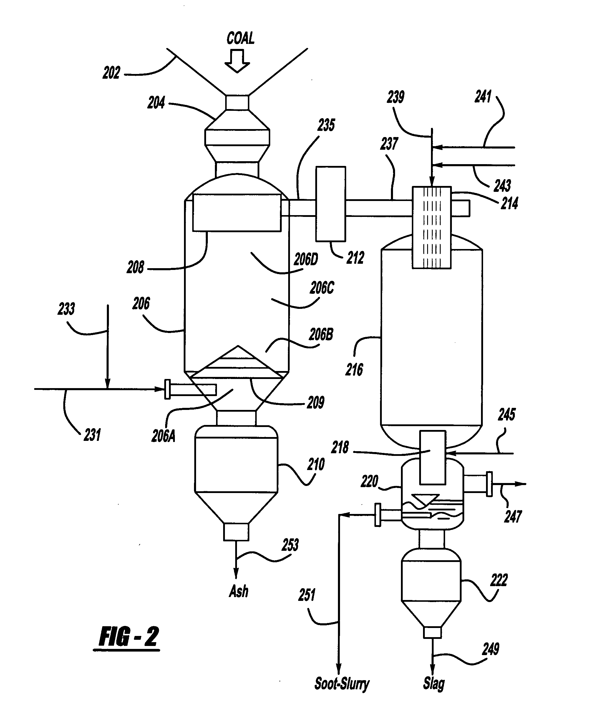
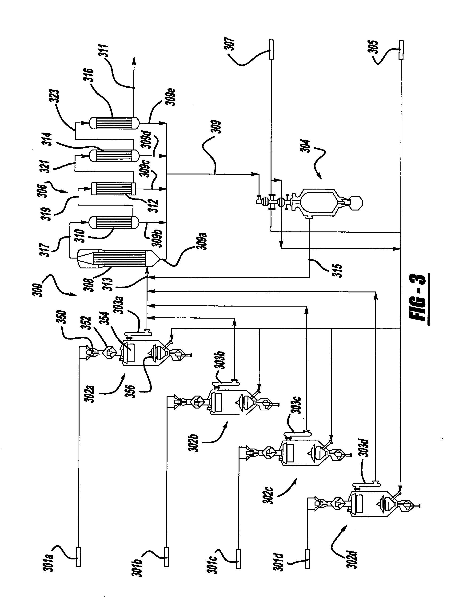
[0055] Unreactive coal (i.e., coal containing more than about 30% non-combustible contaminants) having ash content up to about 50 wt. / % is fed to a primary gasifier arranged as shown in FIGS. 2 or 3 and a primary raw gas is produced at the output of the primary gasifier having a composition by volume percent of 28.2% carbon dioxide, 0.05% hydrogen sulfide, 0.69% higher hydrocarbons, 22.66% carbon monoxide, 38.51% hydrogen, 9.5% methane and 0.39% nitrogen. Raw gas as produced above is then directed to a quenching system wherein the products of pyrolysis and other liquids are condensed out of the gas stream and passed to the input of a non-catalytic partial oxidation unit running at a reaction temperature of about 2578° F. The raw gas from the gasifier is then reformed in the partial oxidation unit, cracked and hydrolysed, and the established process in gasification reaction conditions result in the following typical gas components at the output of the partial oxidation unit expressed...


PUM


Abstract

A process and apparatus for converting a coal into a substitute natural gas generates raw gas in a conventional coal gasification unit and passes at least a portion of the raw gas into a partial oxidation unit to convert the at least portion of the raw gas into a secondary raw synthesis gas substantially devoid of higher hydrocarbons. Optionally, the raw gas is quenched and only the resulting condensate is passed to the partial oxidation unit for conversion to the secondary raw synthesis gas.

Description

BACKGROUND OF THE INVENTION [0001] The invention concerns an apparatus and process for converting coal into a substitute natural gas. More particularly, the invention concerns converting, via non-catalytic partial oxidation, liquid condensates from a primary gasification process into secondary synthesis gas, resulting in utilization of substantially all by-product streams for production of additional raw gas, thereby minimizing undesirable effluent produced by the gasification process. [0002] Coal gasification technology is well known and has been in commercial use, for example, in South Africa for many years. The most commonly employed coal gasifier is that developed by Lurgi Kohle und Mineraloeltechnik GmbH. The Lurgi process utilizes a fixed bed gasifier into which coal of a selected particle size is fed countercurrently to a stream of steam and oxygen. [0003] Coal gasification processes are accompanied by the generation of by-products essentially comprised of oil, tar and phenol...

Claims


Application Information

Patent Timeline
IPC IPC(8): C10J3/00
CPCC01B3/36C01B2203/0255C01B2203/1247C10J3/42C10J3/721C10J3/76C10J2200/156C10J2300/093C10J2300/1846C10K1/08C10K1/101C10K3/005C10K3/008
Inventor VLOK, KARELVAN ZYL, FREDRICO
Owner COGAS LLC
Why Eureka
Try Eureka