Package unit, printed board having the same, and electronic apparatus having the printed board

a technology of heat radiator and package board, which is applied in the direction of insulated conductors, power cables, cables, etc., can solve the problems of difference of thermal expansion coefficient between resin package board and lsi, inability to improve heat transfer efficiency of the whole package, and thermal stress between, so as to achieve simple structure and improve reliability

Inactive Publication Date: 2006-06-01
FUJITSU LTD
View PDF4 Cites 4 Cited by
  • Summary
  • Abstract
  • Description
  • Claims
  • Application Information

AI Technical Summary

Benefits of technology

[0013] Accordingly, it is an exemplified general object of the present invention to provide a package unit having a simple structure, a printed board having the same, and an electronic apparatus having the printed board, which can prevent damages of a joint between the package board and the LSI and a joint between the LSI and the heat spreader and improve the reliability.
[0014] A package unit according to one aspect of the present invention to be mounted on an external printed board includes a package board mounted with an exoergic circuit element, a heat spreader that transmits heat from the exoergic circuit element to a heat sink that radiates the heat, a joining member that seals between the exoergic circuit element and the heat spreader, and forms a sealing space in cooperation with the exoergic circuit element and the heat spreader, and a liquid metal sealed in the sealing space. This package unit thermally connects the exoergic circuit element to the heat spreader through the joining member and liquid metal sealed in the sealing space that is formed by the exoergic circuit element, the heat spreader, and the joining member. Therefore, this package unit shields the thermal stresses caused by the heat from the exoergic circuit element, and maintains a high thermal conductivity.
[0015] The joining member may connect the exoergic circuit element to the heat spreader along an outer circumference of the exoergic element, thereby minimizing the thermal stress applied to the joining member. The heat spreader may include a first member connected to the joining member, and a second member divided from the first member. The heat spreader may include a first member that has a bottom connected to the joining member, and a second member that is engaged with the first member and divided from the first member, the second member having a convex section with a convex facing the exoergic circuit element. Thereby, a simple structure can form a sealing structure that seals the liquid metal.
[0016] The bottom of the first member may serves as a flat spring with a thickness between 200 μm and 1 mm. The second member may have a notch in the convex, the notch permitting a thermal expansion of the liquid metal. Thereby, the stress concentration of the liquid metal can be mitigated. The joining member may be adhesive agent or solid metal.
[0017] The package unit may further include a permission part that permits a thermal expansion of the liquid metal. The permission part may be air sealed in the sealing space. The air may be inert gas that is selected among nitrogen, argon, and helium. The inert gas can prevent chemical reactions of the liquid metal. The permission part may be an elastic member provided in the sealing space. The heat spreader may have a convexoconcave shape on a surface that forms the sealing space. Thereby, the surface area of the heat spreader contacting the liquid metal increases. The heat spreader may be made of an elastic member. The package board may be mounted with plural exoergic circuit elements, and may be made of resin. As discussed above, in comparison with the ceramic board, the resin substrate reduces the cost, provides higher performance, and facilitates processing. In addition, the present invention is particularly effective when a difference of a coefficient of thermal expansion from the exoergic circuit element is big.
[0019] A method according to another aspect of the present invention for manufacturing a package unit to be mounted on an external printed board, the package unit including a heat spreader that transmits heat from the exoergic circuit element mounted on a package board to a heat sink that radiates the heat, the heat spreader including a first member that is connected to the exoergic circuit element, and a second member that is engaged with the first member and forms a sealing space with the exoergic circuit element includes the steps of connecting the exoergic circuit element to the first member via the joining member, injecting a liquid metal between the exoergic circuit element and the first member connected by the connecting step, and engaging the second member with the first member and sealing the liquid metal injected by the injecting space in the sealing space. This manufacturing method can form a sealing structure that seals the liquid metal without high processing technology, and prevents a large size of the sealing structure.

Problems solved by technology

Even when the heat spreader 1700 is made of a material with a high thermal conductivity, such as Cu, the entire package cannot improve the heat transfer efficiency, because the joining layer 1800 needs such a joining material as resin and silicon adhesive agents having a low thermal conductivity or as a sheet or paste joining material, causing a temperature gap.
However, due to a difference of coefficient of thermal expansion between the resin package board and the LSI, the thermal stress occurs between them as the LSI's temperature rises.
In particular, a difference of coefficient of thermal expansion between the resin package board and the LSI is so big that the LSI warps and the heat spreader adhered to the LSI's back surface also warps subject to the influence of warps between the LSI and the package board.
The heat-conductive coating as large as the LSI has no heat dispersion capability and the improved cooling capability for the LSI cannot be expected while its calorific value increases as its performance improves.
Moreover, as described above, the difference of coefficient of thermal expansion between the resin package and the LSI may cause warps in the LSI and damages of the heat-conductive coating.
An expansion of the liquid metal may also cause damages of the heat-conductive coating.
However, this structure becomes big and complex.
In addition, a joint between the heat-conductive coating 2400 and the heat sink 2500 remains problematic as to the thermal conductivity.

Method used


Image

  • Package unit, printed board having the same, and electronic apparatus having the printed board
  • Package unit, printed board having the same, and electronic apparatus having the printed board
  • Package unit, printed board having the same, and electronic apparatus having the printed board

Examples


Embodiment Construction

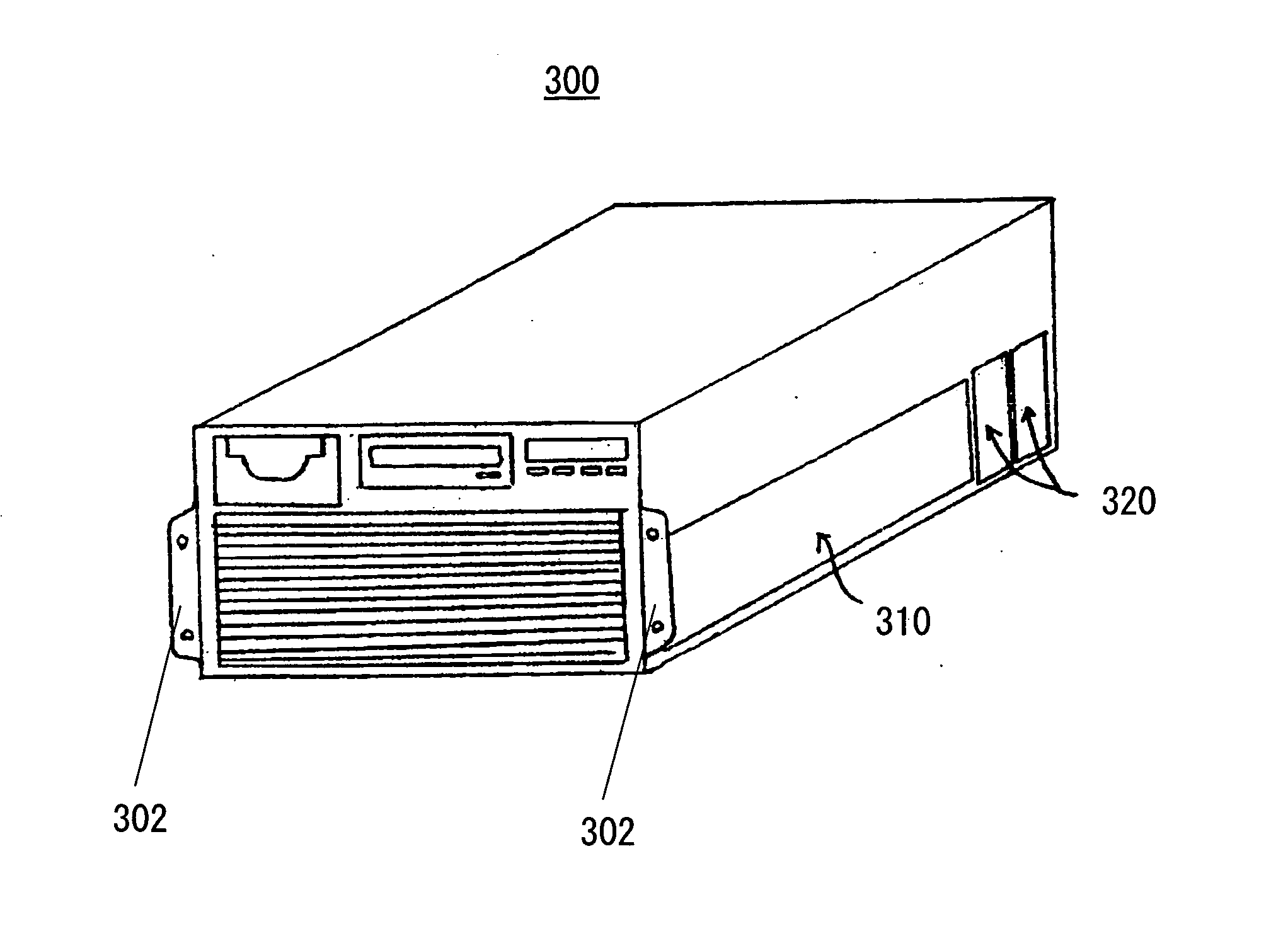
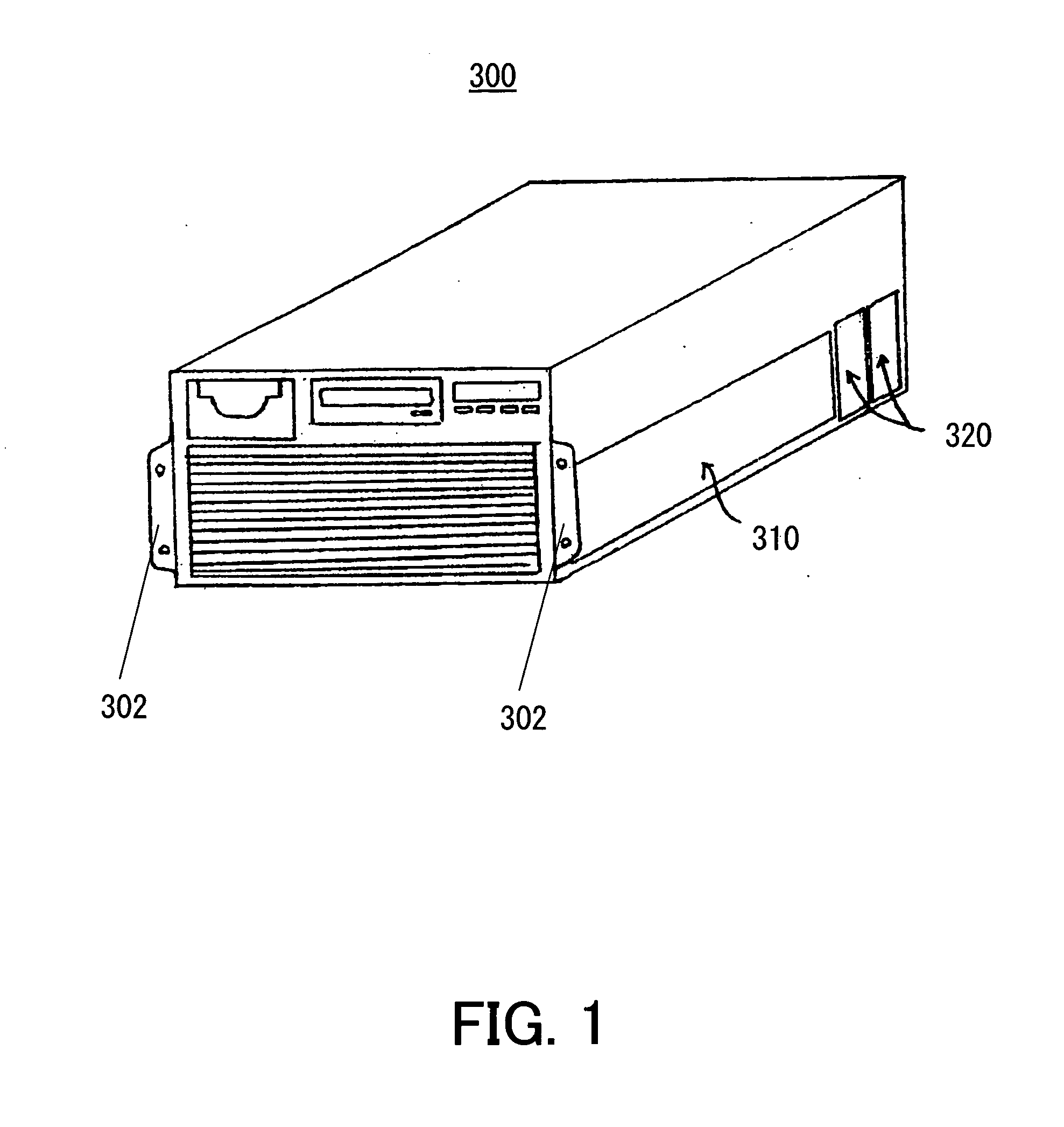
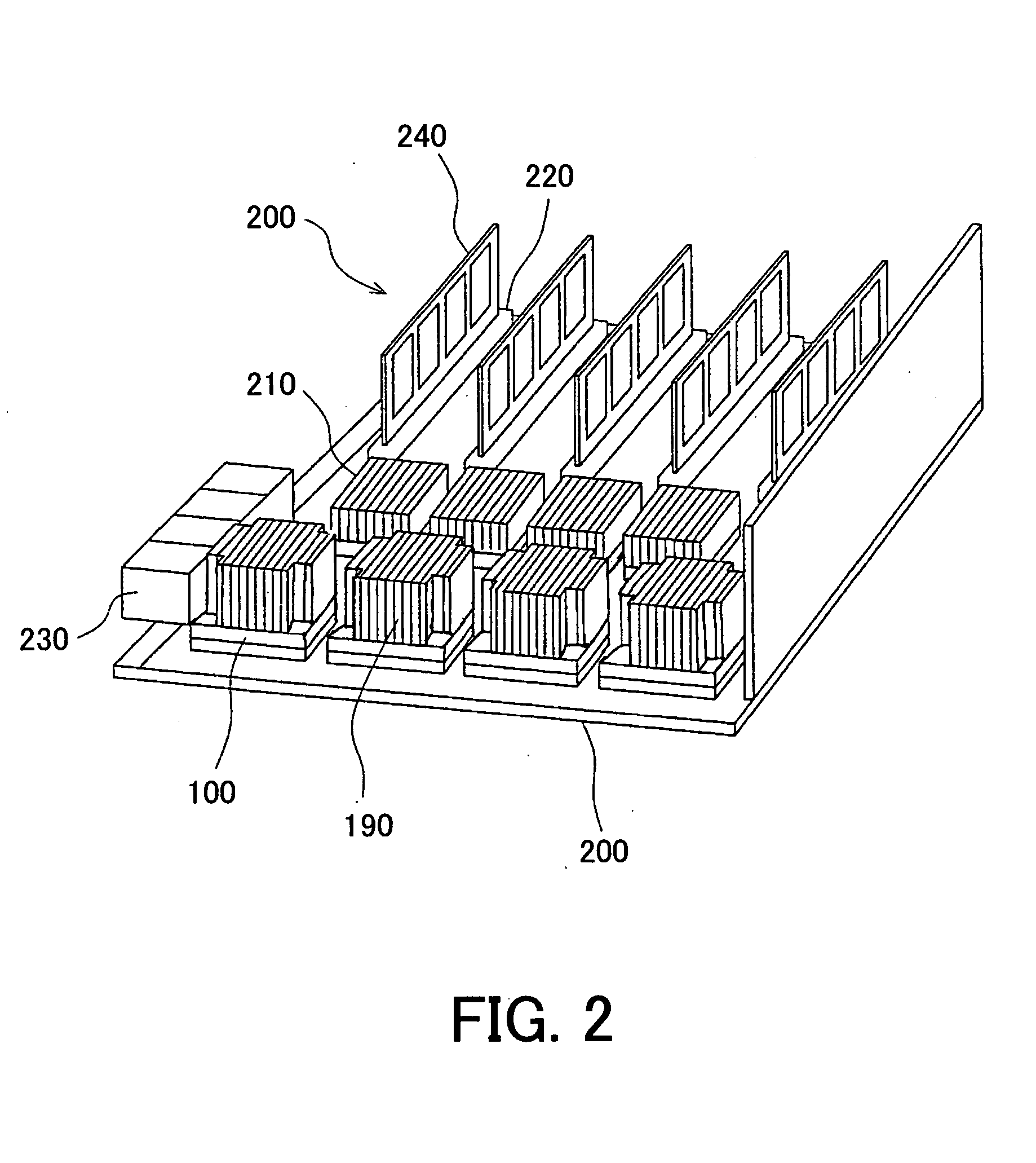
[0038] Referring now to accompanying drawings, a description will be given of a package module 100 as a package unit according to one embodiment of the present invention, a printed circuit board 200 mounted with the package module 100, and an electronic apparatus 300 that includes the printed circuit board 200. Here, FIG. 1 is a schematic perspective view of the electronic apparatus 300. FIG. 2 is a perspective overview of a system board as the printed circuit board 200 included in the electronic apparatus 300. In the following description, a reference numeral with no capital generalizes the reference numeral with a capital.

[0039] As shown in FIG. 1, the electronic apparatus 300 of the instant embodiment is exemplarily implemented as a rack mount type UNIX server. The electronic apparatus 300 is screwed onto a rack (not shown) by a pair of attachment parts 302, and includes the printed circuit board 200 shown in FIG. 2 in a housing 310.

[0040] The housing 310 is provided with a fan...


PUM

PropertyMeasurementUnit
thicknessaaaaaaaaaa
thicknessaaaaaaaaaa
thicknessaaaaaaaaaa

Abstract

A package unit to be mounted on an external printed board includes a package board mounted with an exoergic circuit element, a heat spreader that transmits heat from the exoergic circuit element to a heat sink that radiates the heat, a joining member that seals between the exoergic circuit element and the heat spreader, and forms a sealing space in cooperation with the exoergic circuit element and the heat spreader, and a liquid metal sealed in the sealing space.

Description

[0001] This application is a continuation based on PCT International Application No. PCT / JP2003 / 11014, filed on Aug. 28, 2003, which is hereby incorporated by reference herein in its entirety as if fully set forth herein.BACKGROUND OF THE INVENTION [0002] The present invention relates generally to a fixture of a board, and more particularly to fixture of a package board having a heat radiator mechanism. The present invention is suitable, for example, for a fixture between a heat sink and a Ball Grid Array (“BGA”), a fixture between a heat sink and another package, such as Land Grid Array (“LGA”) and Pin Grid Array (“PGA”). The present invention is also relates to a printed circuit board, such as a motherboard, mounted with such a package board, and an electronic apparatus, such as a server, equipped with the printed circuit board. [0003] The recent developments of electronic apparatuses have increasingly demanded supplies of sophisticated and inexpensive electronic apparatuses. The ...

Claims


Application Information

Patent Timeline
Patent Type & Authority Applications(United States)
IPC IPC(8): H01B9/02H01L23/36H01L23/367H01L23/42H01L23/433H01L23/498
CPCH01L23/3675H01L23/42H01L23/433H01L25/0655H01L2224/27013H01L2224/73253H01L2224/83051H01L2924/0102H01L2924/15311H01L2924/16152H01L2924/16195H01L2924/19106H01L2924/3025H01L2924/3511H01L2224/16225H01L2224/16227H01L2924/01019H01L2224/73204H01L2224/32225H01L2924/00012H01L2924/00
Inventor KUBO, HIDEO
Owner FUJITSU LTD
Why Eureka
Try Eureka