Flip-flop with additional state storage in the event of turn-off

a flip-flop and state storage technology, applied in the field of flip-flops, can solve the problems of loss of storage content after the turn, significant increase in power loss consumption, and latency for swapping and loading storage contents, and achieve the effect of increasing the robustness of the flip-flop, increasing the retention time, and reliably reading out over a longer period of tim

Inactive Publication Date: 2006-06-08
INFINEON TECH AG
View PDF9 Cites 21 Cited by
  • Summary
  • Abstract
  • Description
  • Claims
  • Application Information

AI Technical Summary

Benefits of technology

[0026] This measure prevents an increased leakage current and an unintentional activation of the coupling transistor. If, by way of example, when the flip-flop is switched off, it is disconnected from the VSS potential by an N-MOS power switch, the virtual VVSS terminal drifts in the direction of the VDD potential. If the capacitance is connected by its second terminal to the VVSS terminal instead of to the VDD terminal, the potential of the storage node, that is to say the potential at the first terminal of the capacitance, drifts by the same magnitude, thus resulting in a potential elevation at the storage node (also referred to as “pushing”), as a result of which the leakage current of the P-MOS coupling transistor increases and the P-MOS coupling transistor is possibly even activated.
[0027] The latch stage is advantageously embodied using differential circuit technology. In this case, two memory cells are provided in the flip-flop, the two memory cells being driven complementarily with respect to one another via the data input. In this case, the memory cells are read differentially, thereby increasing the robustness of the flip-flop towards interference signals. In particular so-called soft errors caused by radiation, which are typical both of static and of dynamic storage concepts, are avoided to the greatest possible extent by virtue of the differential circuit concept of the flip-flop. It holds true in this case that the flip-flop according to the invention is generally, that is to say also in a non-differential embodiment, less sensitive towards radiation since only one radiation-sensitive pn junction is present at the storage node, whereas 4 to 8 pn junctions are present at the storage nodes in the case of state retention flip-flops known from the prior art. The differential storage concept additionally serves for increasing the retention time, since storage contents attenuated by leakage currents can be reliably read out over a longer period of time.

Problems solved by technology

What is disadvantageous about the turn-off of a circuit block is that circuit parts situated within the circuit block that effect storage, such as, for example, flip-flops, memory cells or memory arrays, lose their storage content after the turn-off.
The use of state retention flip-flops is preferable to a SRAM-based solution since the latter is associated with a significantly increased power loss consumption and a latency for swapping and loading the storage contents.
What is disadvantageous about forms of implementation of a state retention flip-flop that are known from the prior art is that such state retention flip-flops within a circuit block have to be supplied not with two supply potentials but rather with at least three supply potentials, namely with the virtual supply potential VVDD or VVSS and the two non-connected supply potentials VDD and VSS.
In view of the limited number of metallization planes, considerable limitations for the remaining wiring result on account of the additional supply rail.
Moreover, further disadvantages for the layout result form the use of the additional supply potential; by way of example, a well isolation is required in the layout.
A further problem results from the fact that the nodes between the turned-off circuit parts and the shadow latch have a non-defined, floating potential, which would lead to high short-circuit currents into the shadow latch.

Method used


Image

  • Flip-flop with additional state storage in the event of turn-off
  • Flip-flop with additional state storage in the event of turn-off
  • Flip-flop with additional state storage in the event of turn-off

Examples


Embodiment Construction

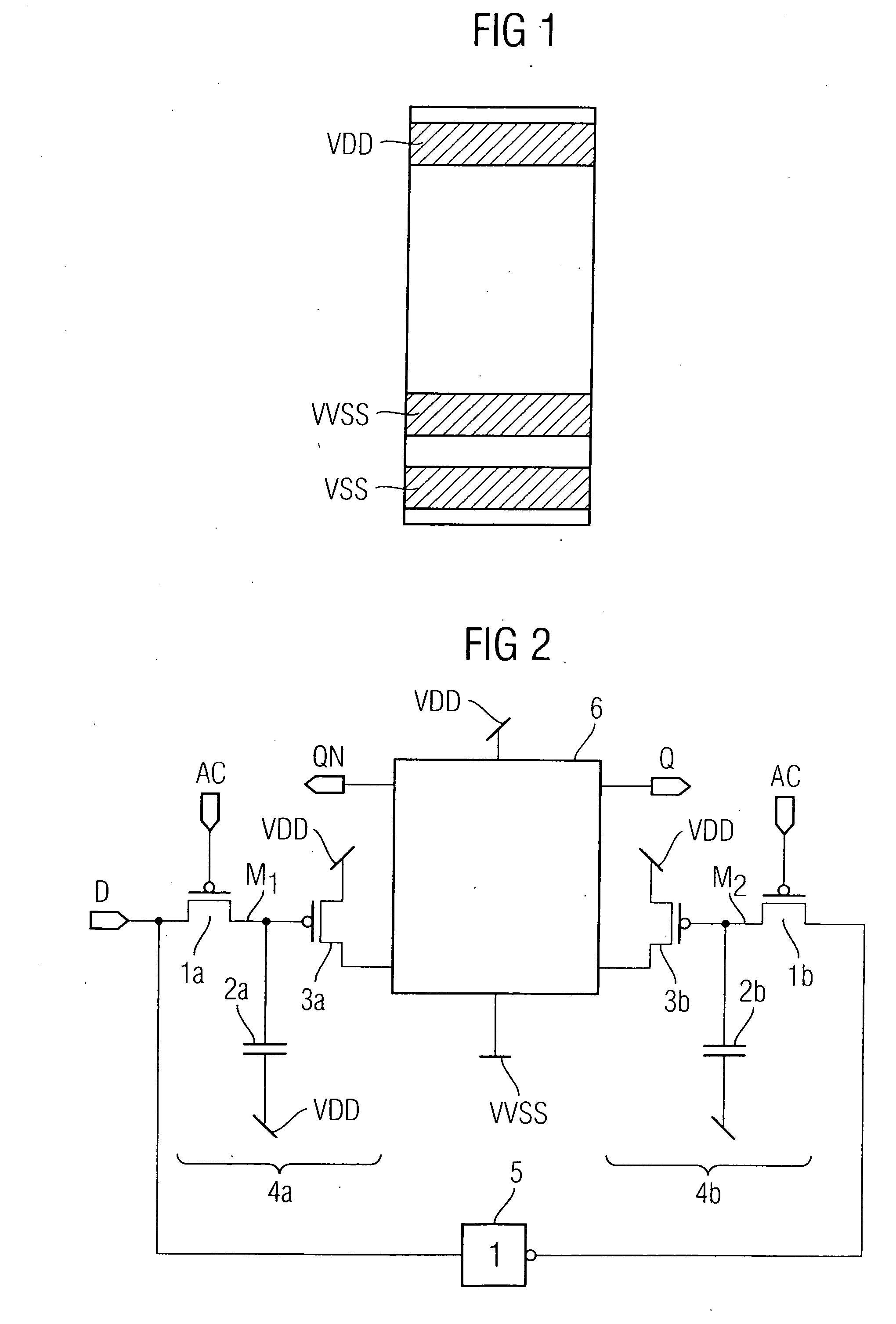
[0054] With regard to FIG. 1 concerning the prior art, reference is made to the explanations in the introduction to the description.

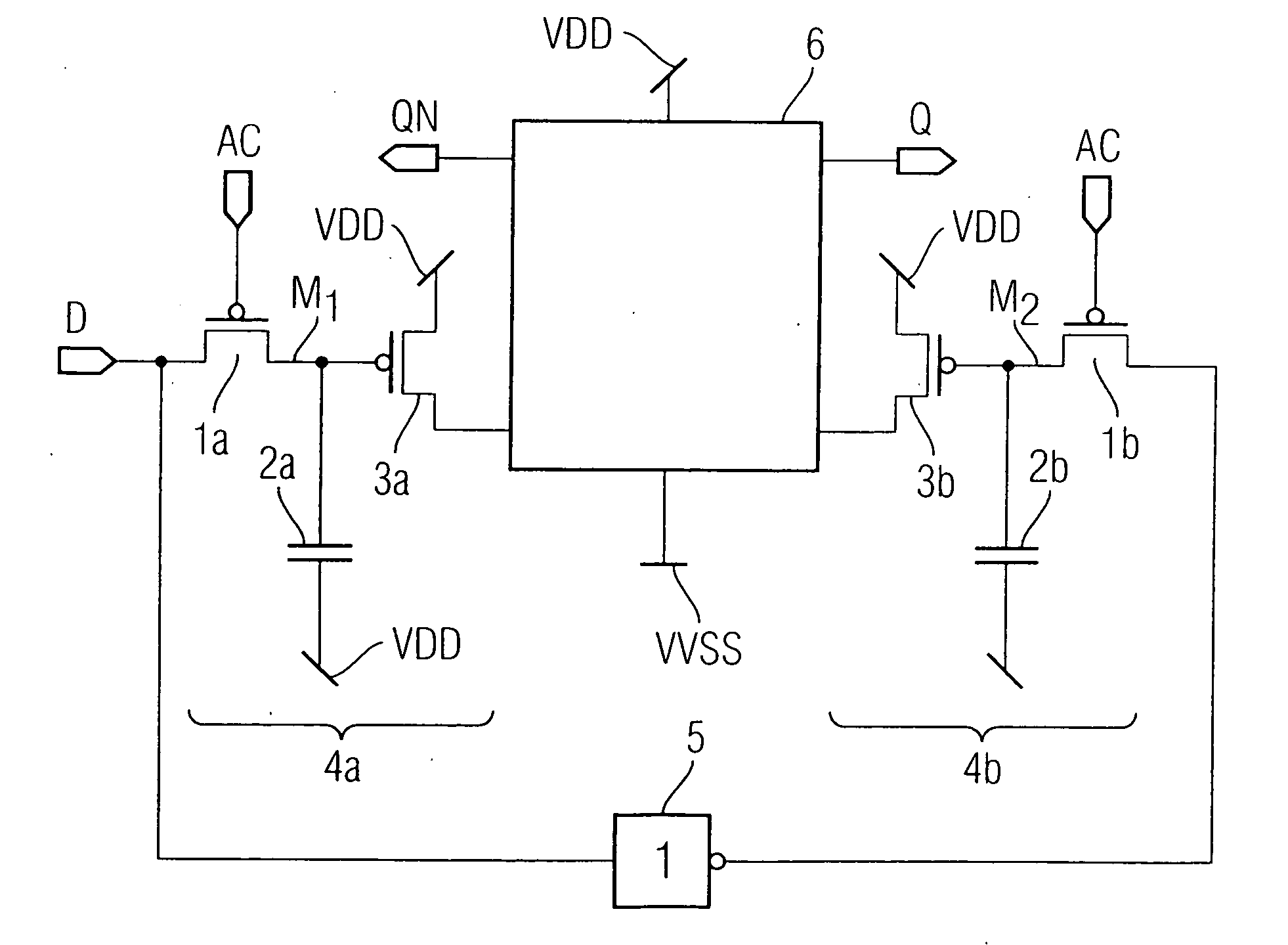
[0055]FIG. 2 illustrates a basic circuit diagram of an exemplary embodiment of an edge-triggered state retention flip-flop according to the invention, which can be used in a circuit block that can be turned off by means of an N-MOS power switch. As explained above, state retention flip-flops known from the prior art for state storage, in the turned-off state of the flip-flop, use an additional static latch stage which is continuously switched on. The differential state retention flip-flop according to the invention as illustrated in FIG. 2 is based, by contrast, on two dynamic memory cells 4a / 4b, each comprising a P-MOS coupling transistor 1a / 1b a storage capacitance 2a / 2b and a P-MOS storage transistor 3a / 3b. For the coupling transistors 1a / 1b and the storage transistors 3a / 3b, use is preferably made of thick oxide transistors having at the same time ...


PUM


Abstract

The flip-flop according to the invention serves for storing an item of logic state information and has at least one data input and at least one data output. The flip-flop comprises at least one latch stage for storing the state information if the flip-flop is switched on. Furthermore, the flip-flop according to the invention comprises at least one memory cell having a capacitance as storage element. In this case, the at least one memory cell serves for storing the state information if the flip-flop is switched off.

Description

CROSS-REFERENCE TO RELATED APPLICATIONS [0001] This application claims foreign priority benefits under 35 U.S.C. §119 to co-pending German patent application number DE 10 2004 055 006.9, filed 15 Nov. 2004. This related patent application is herein incorporated by reference in its entirety.BACKGROUND OF THE INVENTION [0002] 1. Field of the Invention [0003] The invention relates to a flip-flop for storing logic state information in a circuit block, which retains the state information when the flip-flop and the surrounding circuit block are turned off. [0004] 2. Description of the Related Art [0005] In order to reduce the power loss of a system, it is known to turn off circuit blocks, in particular logic blocks, which are temporarily not required for the function of the system. In general, the respective circuit block is turned off by decoupling the circuit block from the supply voltage. In order to isolate the respective circuit block from the negative pole (VSS; e.g. 0 V) of the sup...

Claims


Application Information

Patent Timeline
Patent Type & Authority Applications(United States)
IPC IPC(8): H03K3/356
CPCG11C11/412
Inventor HENZLER, STEPHANBERTHOLD, JOERGGEORGAKOS, GEORGSCHMITT-LANDSIEDEL, DORISPACHA, CHRISTIAN
Owner INFINEON TECH AG
Why Eureka
Try Eureka