Collector optical system, light source unit, illumination optical apparatus, and exposure apparatus

Active Publication Date: 2006-06-08
NIKON CORP
View PDF6 Cites 38 Cited by
  • Summary
  • Abstract
  • Description
  • Claims
  • Application Information

AI Technical Summary

Benefits of technology

[0019] The present invention has been accomplished in light of the above problem and an object of the invention is to construct a collector optical system so that the plasma does not absorb the EUV light reflect

Problems solved by technology

Therefore, the collector optical system of FIG. 2 can

Method used


Image

  • Collector optical system, light source unit, illumination optical apparatus, and exposure apparatus
  • Collector optical system, light source unit, illumination optical apparatus, and exposure apparatus
  • Collector optical system, light source unit, illumination optical apparatus, and exposure apparatus

Examples


embodiment 1

[0049] Embodiments of the present invention will be described on the basis of the accompanying drawings.

[0050]FIG. 3 shows a light source unit being an embodiment of the present invention.

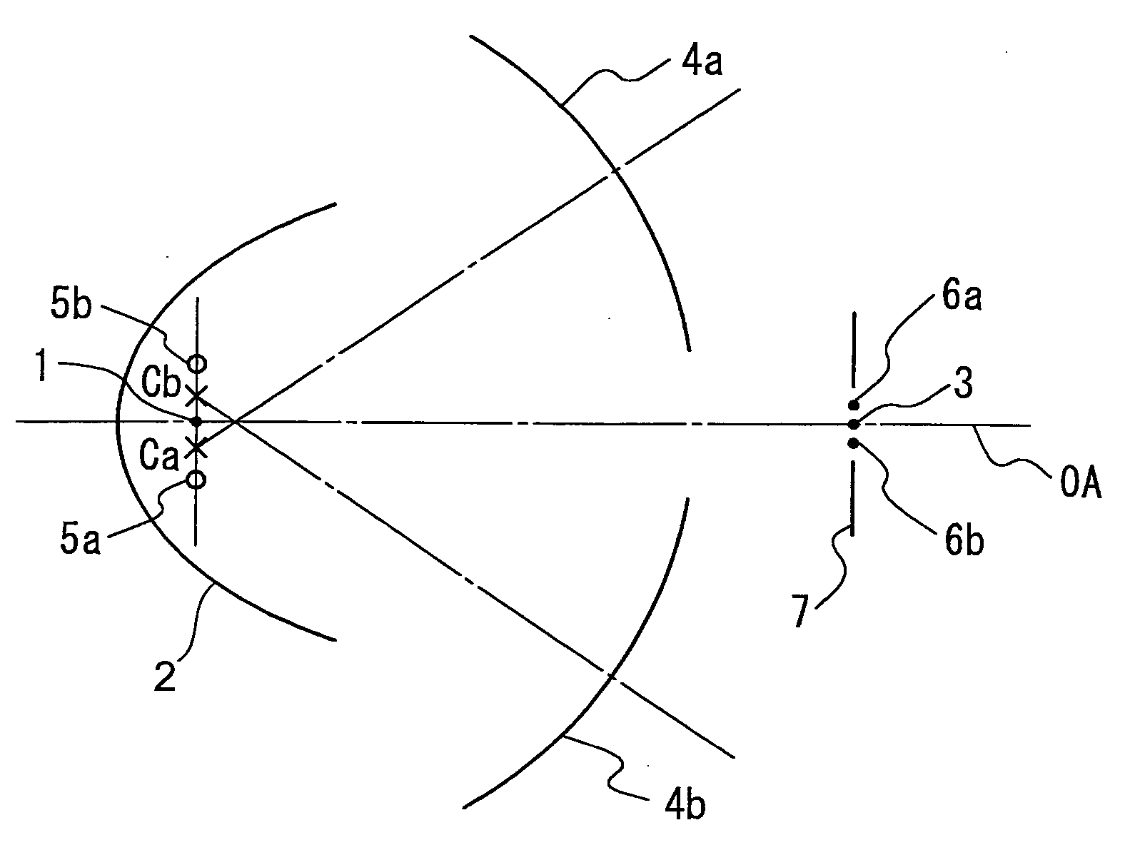
[0051] A plasma light source 1 is located at the first focal point of collective mirror 2 having a reflecting surface shaped in an ellipsoid of revolution (i.e., at a focal point of the ellipsoid). Auxiliary collective mirror elements 4a, 4b are arranged as inclined so that respective spherical centers Ca, Cb thereof are displaced by ±0.25 mm, respectively, in the direction perpendicular to the optical axis OA from the position of the plasma light source 1. Part of the EUV light emitted from the plasma light source 1 is reflected by the collective mirror 2 to form a light source image 3 on the second focal plane of the ellipsoid.

[0052] Other part of the EUV light emitted from the plasma light source 1 is reflected by the auxiliary collective mirror elements 4a, 4b to form light source images 5a,...

embodiment 3

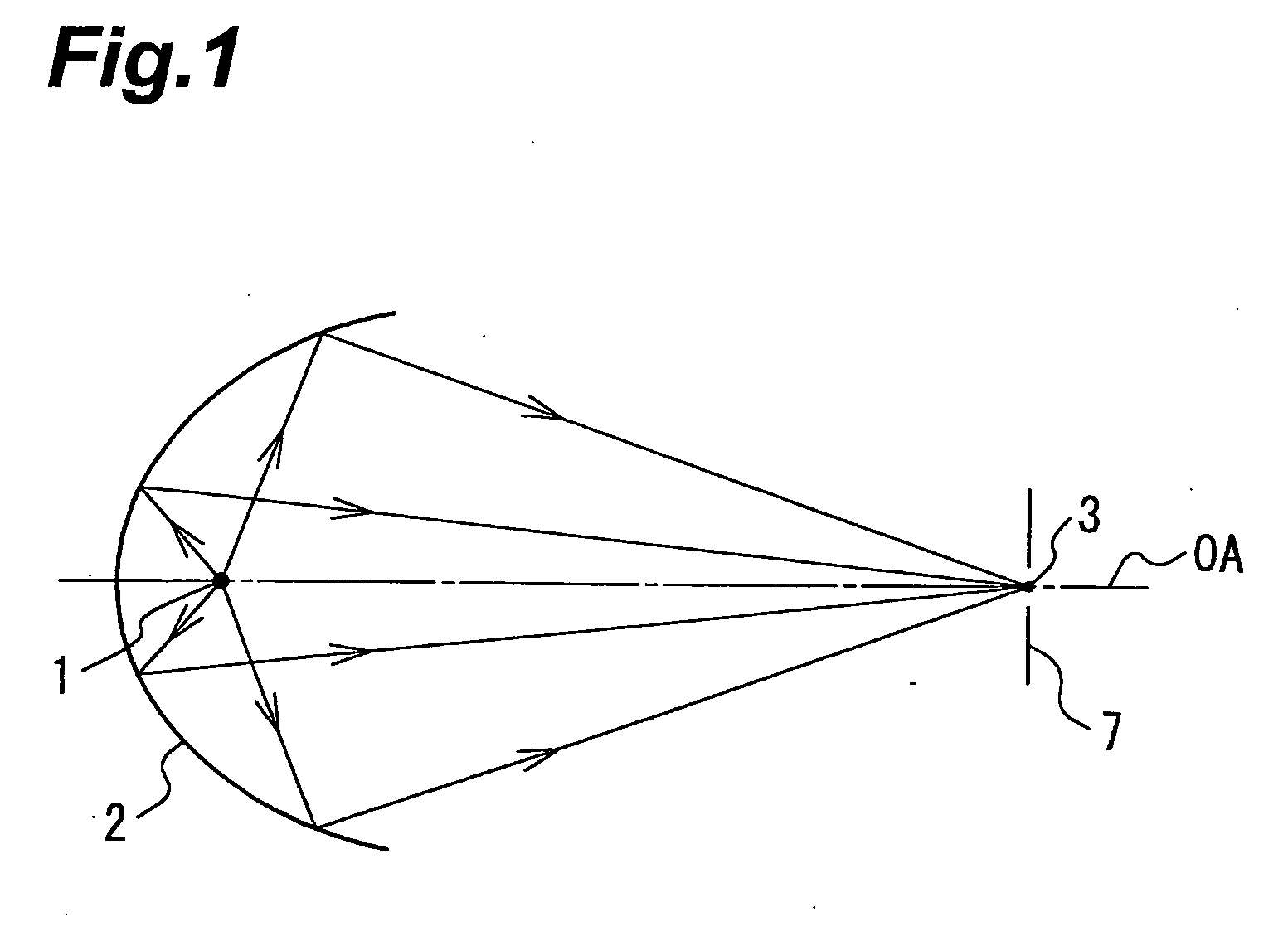
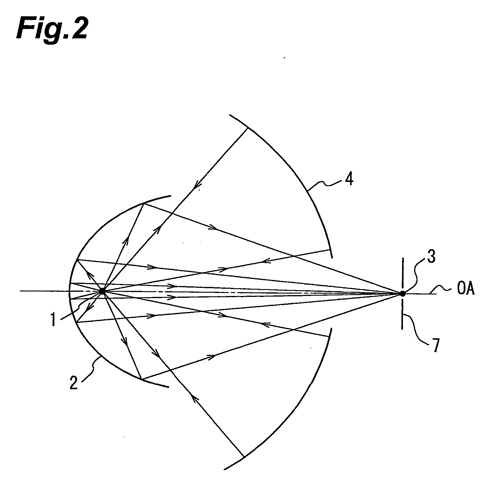
[0059]FIG. 7 shows a light source unit being an embodiment of the present invention. Referring to FIG. 7, the plasma light source 1 is arranged to collect light emitted from a laser light source LS (non-EUV light), through a lens 12 and a through-hole of collective mirror 2. The plasma light source 1 is located at the first focal point of collective mirror 2 having a reflecting surface shaped in an ellipsoid of revolution. There is an auxiliary collective mirror 4 having a reflecting surface of a spherical shape centered on the position of the first focal point. Part of the EUV light emitted from the plasma light source 1 is reflected by the collective mirror 2 to form a light source image 3 on the second focal plane of the ellipsoid. Other part of the EUV light emitted from the plasma light source 1 is reflected by the auxiliary collective mirror 4 to form a light source image 3 at the same position as the plasma light source 1 is located. The distance from the plasma light source ...

embodiment 4

[0060]FIG. 8 shows an embodiment of an EUV exposure apparatus incorporating an illumination optical system using the light source unit being the first embodiment of the present invention, and a rod type optical integrator proposed by Applicant of the present application et al. (Japanese Patent Application No. 2000-068114).

[0061]FIG. 8 is an illustration showing a schematic configuration of a first projection exposure apparatus according to the present embodiment, and the projection exposure apparatus is roughly composed of a light source unit LU, an illumination optical system IU, and a projection optical system PL. These are located in a vacuum state in a chamber, or in a chamber filled with a gas (e.g., helium) demonstrating little absorption to at least a wavelength to be used.

[0062] With reference to FIG. 8, the plasma light source 1 is arranged so that light emitted from a laser light source LS (non-EUV light) is collected through a lens 12 and a through-hole of collective mi...


PUM


Abstract

A light source unit of EUV light is provided as a light source unit comprising a plasma light source for emitting EUV light, a collective mirror which has a reflecting surface of an ellipsoid of revolution and at a first focal point of which the plasma light source is located, and an auxiliary collective mirror which has a reflecting surface of a spherical surface and a spherical center of which is located as displaced from a position of the plasma light source.

Description

CROSS-REFERENCE TO RELATED APPLICATIONS [0001] This is a continuation-in-part application of application serial no. PCT / JP2004 / 010053 filed on Jul. 14, 2004, now pending, and incorporated by reference in its entirety.FIELD OF THE INVENTION [0002] The present invention relates to a collector optical system, illumination optical apparatus, and exposure apparatus. More particularly, the present invention relates to a collector optical system suitably applicable to the exposure apparatus used in production of microdevices such as semiconductor elements by photolithography, using EUV light (Extreme UltraViolet light) having the wavelength of approximately 5-50 nm. RELATED BACKGROUND ART [0003] The exposure apparatus for production of semiconductor devices is arranged to project and transcribe a circuit pattern formed on a mask, onto a photosensitive substrate such as a wafer coated with a resist, through a projection optical system. [0004] With the exposure apparatus of this type, there ...

Claims


Application Information

Patent Timeline
IPC IPC(8): H01S3/08G21K1/06G03F7/20G21K5/00G21K5/02H01L21/027H05G2/00
CPCG03F7/70033G03F7/70175G02B19/0047
Inventor MURAKAMI, KATSUHIKO
Owner NIKON CORP
Why Eureka
Try Eureka