Carrier, two-component developer, and image forming method

a two-component, carrier technology, applied in the direction of developers, instruments, optics, etc., can solve the problems of surface wear, affecting the image quality of the member, fog or density drop, etc., to achieve stable image formation, high minuteness, and superior charge-providing performance

Inactive Publication Date: 2006-06-15
CANON KK
View PDF1 Cites 8 Cited by
  • Summary
  • Abstract
  • Description
  • Claims
  • Application Information

AI Technical Summary

Benefits of technology

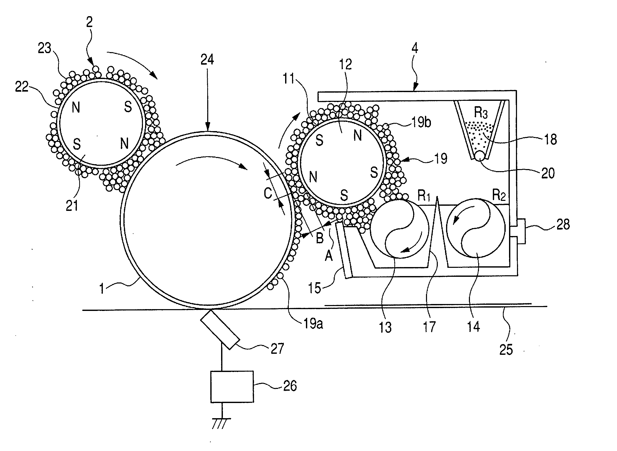
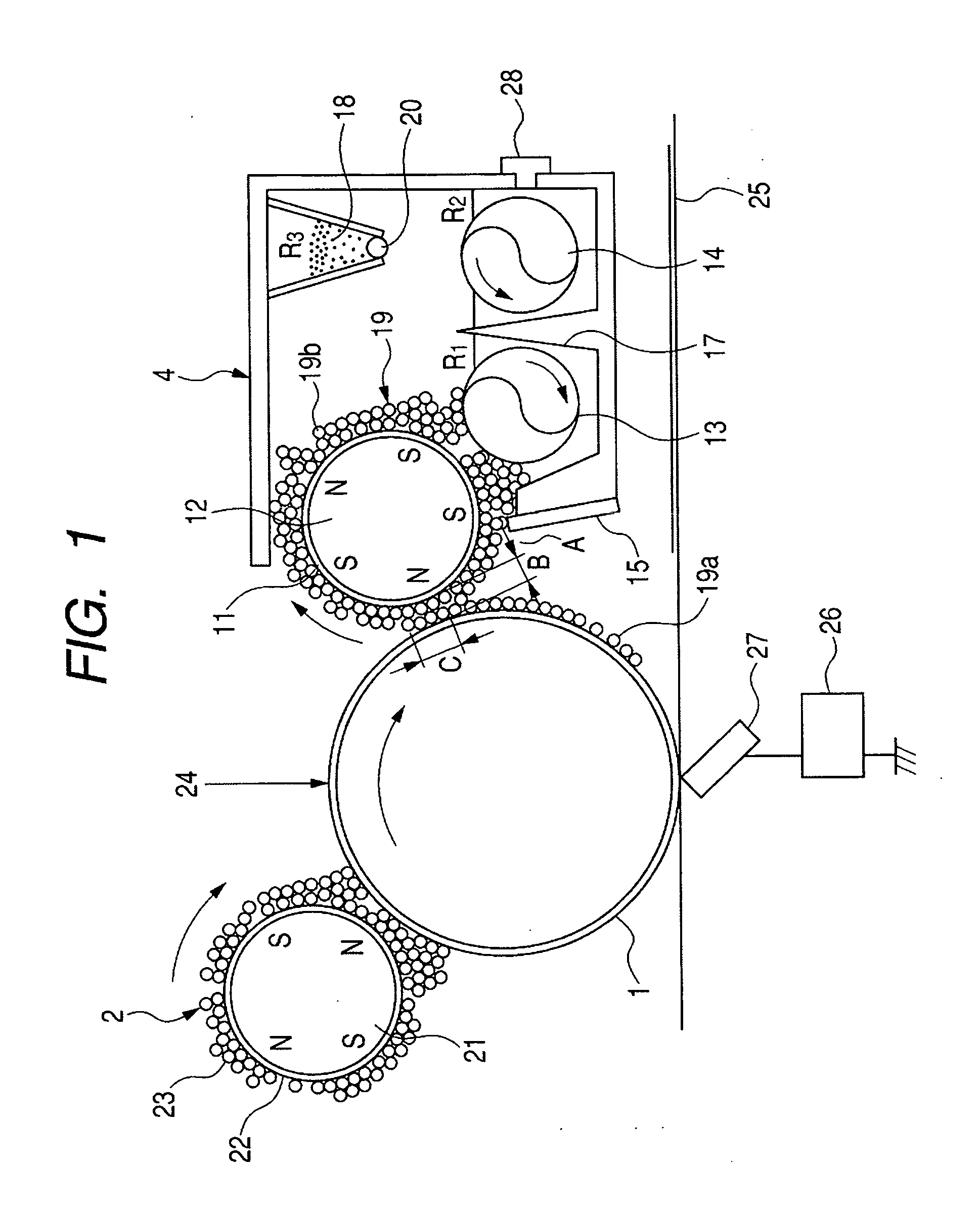
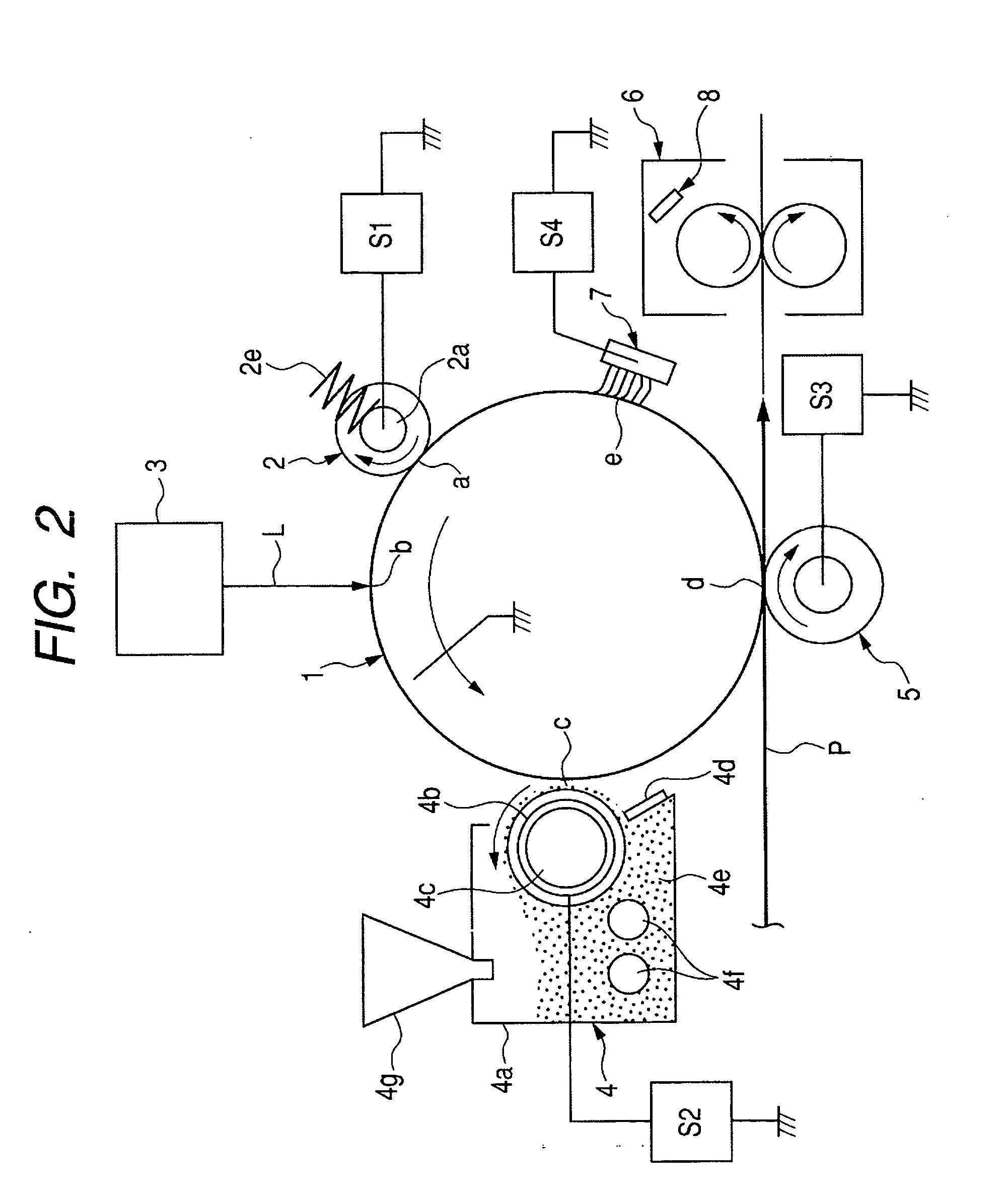
[0019] An object of the present invention is to provide a carrier which has solved the above problems and can contribute to the stable formation of images having satisfied high minuteness. More specifically, it is to provide a magnetic carrier which is adaptable also to the cleanerless system, has a superior charge-providing performance, also has a broad latitude against can contribute to high-quality images free of fog and density non-uniformity over a wide range of from low area percentage images to high area percentage images, also has a superior environmental stability, and still also has a high running performance, and to provide a two-component developer and an image forming process which make use of such a magnetic carrier.
[0048] The magnetic carrier of the present invention can contribute to the stable formation of images having satisfied high minuteness. More specifically, it is adaptable also to the cleanerless system, has a superior charge-providing performance, also has a broad latitude against carrier-spent, can contribute to high-quality images free of fog and density non-uniformity over a wide range of from low area percentage images to high area percentage images, also has a superior environmental stability, and still also can have a high running performance.

Problems solved by technology

Hence, because of the fact that the member constituting such a cleaning means is brought into pressure touch with the surface of the photosensitive member, problems have tended to arise.
For example, bringing a cleaning member into strong pressure touch causes the surface of the photosensitive member to wear.
This has been a bottleneck in attempts to make apparatus compact.
This is namely because making toners have a smaller particle diameter makes the toners have a larger particle surface area, resulting in a broad charge quantity distribution, and this tends to cause fog.
When such toners having a small particle diameter are used in high-speed machines, excess charging may result especially in an environment of low humidity to cause fog or a decrease in density.
Where such toners having a small particle diameter are used, faulty cleaning tends to occur in a system in which the transfer residual toner on the photosensitive member is removed by cleaning.
On the other hand, in the above cleanerless system, transfer residual toner due to fogging toner may increase, and its presence may inhibit the photosensitive member from being charged at its charging portions, to cause fog more seriously, making it difficult to provide high-grade images.
In an aspect of image quality, in the case of the corona charging, it has come about that the toner having scattered tends to contaminate charging wires to make their discharge insufficient at the areas thus contaminated, and this makes it difficult for the photosensitive member (drum) to be provided with a stated potential.
Hence, an image defect called line images tends to occur in the contact charging system as well, a charging system in which an alternating current is applied superimposingly on direct-current charging is employed from the viewpoint that the photosensitive member which is a latent image baring member is to be sufficiently charged over a long period of time.
Where the toner has adhered to the charging member, it causes faulty-charging.
Both the cases result in image defects corresponding to the areas to which the toner has adhered.
Thus, although various proposals have been made as systems, some problems still remain unsolved in regard to developers suited for the matching with such systems.
As to the iron powder carrier among these, the carrier has so low a specific resistance that electric charges of electrostatic latent images may leak through the carrier to disorder the electrostatic latent images to cause image defects.
However, although the developer can be made to have a long lifetime, such a carrier may have an insufficient uniformity in magnetic properties.
Hence, this has tended to cause carrier adhesion to tend to cause image defects.
In that case, however, the carrier has so large a specific gravity and further has so large a saturation magnetization that it may provide a rigid magnetic brush to have tended to cause deterioration of the developer, such as carrier-spent and deterioration of external additives of toner, and also cause sweep marks of the magnetic brush.
However, these are all ferrite carriers constituted of only light metals, and their constituents have a poor mutual adhesion to have an insufficient particle strength.
Hence, irregular-shape particles tend to be present to tend to cause faulty images.
Such a method, however, may cause coalescence between particles to tend to cause faulty images.
Hence, the charging of toner may rise so excessively as to provide insufficient image density or cause ground fog.
In this method, however, layers that form the microscopic unevenness may come off as a result of long-term service to cause a problem on durability of the carrier.

Method used


Image

  • Carrier, two-component developer, and image forming method
  • Carrier, two-component developer, and image forming method
  • Carrier, two-component developer, and image forming method

Examples


example 1

[0221] Carrier 1 (93 parts by weight) and the cyan toner Toner 1 (7 parts by weight) which were obtained as above were blended at 38 rpm for 3 minutes by means of a V-type mixer to prepare Developer 1.

[0222] Next, this Developer 1 was evaluated in the following way. As an evaluation machine, iRC3200 (manufactured by CANON INC.) was used. A 8,000-sheet image reproduction test was conducted using CLC 80 g paper (available from CANON SALES CO., INC.), in a monochromatic mode, in a normal-temperature and normal-humidity environment (23° C / 60% RH; hereinafter also “N / N”) and using an original having a low image area percentage of 3%, to make evaluation, and thereafter a 2,000-sheet image reproduction test was further conducted in the same way but using an original having a high image area percentage of 20%, to make evaluation. The like evaluation was also made in a high-temperature and high-humidity environment (32.5° C. / 90% RH; hereinafter also “H / H”). The evaluation was made by the fo...

examples 2 to 12

[0255] Developers 2 to 12 were produced in the same manner as the production of Developer 1 except that the carriers were changed as shown in Table 3. Evaluation was made in the same way. The results are shown in Table 3.

example 13

[0256] Developer 13 was produced in the same manner as the production of Developer 12 except that the toner was changed as shown in Table 3. Evaluation was made in the same way. The results are shown in Table 3.


PUM

PropertyMeasurementUnit
particle diameteraaaaaaaaaa
number-average primary particle diameteraaaaaaaaaa

Abstract

In a carrier comprising carrier particles; each carrier particle comprising a carrier core and a coat layer for coating the carrier core, the carrier core has a ferrite component containing i) a metal oxide having at least one of metallic elements Mg, Li and Ca, the total-sum content of which is 10 to 40 mole % based on the whole ferrite component, and ii) a metal oxide having at least one of metallic elements Mn, Cu, Cr and Zn, the total-sum content of which is 50 to 4,000 ppm based on the whole ferrite component. The carrier has a volume distribution based 50% particle diameter (D50) of from 15.0 to 55.0 μm and a degree of surface unevenness of from 1.05 to 1.30, and the coat layer contains particles; the particles having a number-average primary particle diameter of from 10 to 500 nm.

Description

BACKGROUND OF THE INVENTION [0001] 1. Field of the Invention [0002] This invention relates to a carrier used in a developer for developing electrostatic latent images in electrophotography, electrostatic recording, electrostatic printing or toner jet recording, a two-component developer having the carrier and a toner, and an image forming method making use of the two-component developer. [0003] 2. Related Background Art [0004] A number of methods are known as methods for image forming processes. In particular, it is common to use an image forming method like the following: First, an electrostatic latent image is formed on a photosensitive member by various means utilizing a photoconductive material. Subsequently, the latent image is developed by the use of a toner to form a toner image as a visible image. Then, the toner image is transferred to a recording material such as paper as occasion calls, and thereafter the toner image is fixed by the action of heat and / or pressure to obtai...

Claims


Application Information

Patent Timeline
Patent Type & Authority Applications(United States)
IPC IPC(8): G03G9/113
CPCG03G9/10G03G9/107G03G9/1075G03G9/1134G03G9/1135G03G9/1136G03G9/1137G03G9/1085
Inventor HOTTA, YOJIROIDA, TETSUYAIIDA, WAKASHIHASHIMOTO, AKIRAKOMATSU, NOZOMUBABA, YOSHINOBU
Owner CANON KK
Why Eureka
Try Eureka