[0014] Another embodiment of the invention comprises an expandable transluminal access sheath adapted for providing minimally invasive access to the
gastrointestinal tract through a working channel of an
endoscope. An axially elongate sheath tube is provided with a proximal end, a distal end, and a central through lumen. A distal region of the sheath is expandable, in response to outward pressure applied therein, to a
diameter which is larger than that of a proximal region of the sheath. A hub is affixed to the proximal end of the sheath tube. The hub is adapted to facilitate the passage of
instrumentation.
[0015] A need therefore remains for improved
access technology, which allows a device to be transesophageally, passed through the
esophagus and
stomach into the
small intestine with a small introduction
diameter, while accommodating the introduction of relatively large
diameter instruments. It would be beneficial if a gastroenterologist did not need to inventory and use a range of
catheter diameters. It would be far more useful if one
catheter diameter could fit the majority of patients. Ideally, the
catheter would be able to enter a vessel or body lumen with a diameter of 3 to 12 French or smaller, and be able to pass instruments through a central lumen that is 14 to 20 French. The sheath would be capable of gently dilating the papilla
sphincter and of permitting the exchange of
instrumentation therethrough without being removed from the body. The sheath would also be maximally visible under
fluoroscopy and would be relatively inexpensive to manufacture. The sheath or catheter would be kink resistant and minimize abrasion and damage to instrumentation being passed therethrough. The sheath or catheter would further minimize the potential for injury to body lumen or cavity walls or surrounding structures.
[0016] One embodiment of the present invention comprises a transluminal radially expanding access sheath. The radially expanding access sheath is used to provide selective access to the common
bile duct or the
pancreatic duct. In an embodiment, the sheath would have an introduction outside diameter that ranged from 3 to 12 French with a preferred range of 5 to 10 French. The diameter of the sheath would be expandable to permit instruments
ranging up to 30 French to pass therethrough, with a preferred range of between 3 and 20 French. The sheath can have a working length
ranging between 150-cm and 300-cm with a preferred length of 175-cm to 225-cm. The ability to pass the large traditional instruments and smaller more innovative instruments through a catheter introduced with a small outside diameter is derived from the ability to expand the distal end of the catheter to create a larger through lumen. The expandable distal end of the catheter can comprise 75% or more of the overall working length of the catheter. The proximal end of the catheter is generally larger than the distal end to provide for pushability, control, and the ability to pass large diameter instruments therethrough. In an embodiment, the sheath can be routed to its destination over or alongside one or more already placed guidewires with a diameter
ranging up to 0.040 inches.
[0017] Another embodiment of the invention comprises a transluminal access
system for providing minimally invasive access to gastroenterological structures. The
system includes an access sheath comprising an axially elongate tubular body that defines a lumen extending from the proximal end to the distal end of the sheath. At least a portion of the distal end of the elongate tubular body is expandable from a first, smaller cross-sectional profile to a second, greater cross-sectional profile. In an embodiment, the first, smaller cross-sectional profile is created by making axially oriented folds in the sheath material. These folds may be located in only one circumferential position on the sheath, or there may be a plurality of such folds or longitudinally oriented crimps in the sheath. The folds or crimps may be made permanent or semi-permanent by heat-setting the structure, once folded. In an embodiment, a releasable jacket is carried by the access sheath to restrain at least a portion of the elongate tubular structure in the first, smaller cross-sectional profile. In another embodiment, the jacket is removed prior to inserting the sheath into the patient. In an embodiment, the elongate tubular body is sufficiently pliable to allow the passage of objects having a maximum cross-sectional size larger than an inner diameter of the elongate tubular body in the second, greater cross-sectional profile. The adaptability to objects of larger dimension is accomplished by
pliability or re-shaping of the cross-section to the larger dimension in one direction accompanied by a reduction in dimension in a lateral direction. The adaptability may also be generated through the use of malleable or elastomerically deformable sheath material.
[0020] In another embodiment of the invention, it is advantageous that the sheath comprise a radiopaque marker or markers. The radiopaque markers may be affixed to the non-expandable portion or they may be affixed to the expandable portion. Markers affixed to the radially expandable portion preferably do not restrain the sheath or catheter from radial expansion or collapse. Markers affixed to the non-expandable portion, such as the catheter shaft of a
balloon dilator may be simple rings that are not radially expandable. Radiopaque markers include shapes fabricated from malleable material such as gold,
platinum,
tantalum,
platinum iridium, and the like. Radiopacity can also be increased by vapor deposition
coating or plating
metal parts of the catheter with metals or alloys of gold,
platinum,
tantalum, platinum-
iridium, and the like. Expandable markers may be fabricated as undulated or wavy rings, bendable wire wound circumferentially around the sheath, or other structures such as are found commonly on stents, grafts or catheters used for endovascular access in the body. Expandable radiopaque structures may also include disconnected or incomplete surround shapes affixed to the surface of a sleeve or other expandable shape. Non-expandable structures include circular rings or other structures that completely surround the catheter circumferentially and are strong enough to
resist expansion. In another embodiment, the polymeric materials of the catheter or sheath may be loaded with radiopaque filler materials such as, but not limited to,
bismuth salts, or
barium salts, or the like, at percentages ranging from 1% to 50% by weight in order to increase radiopacity. The radiopaque markers allow the sheath to be guided and monitored using
fluoroscopy.
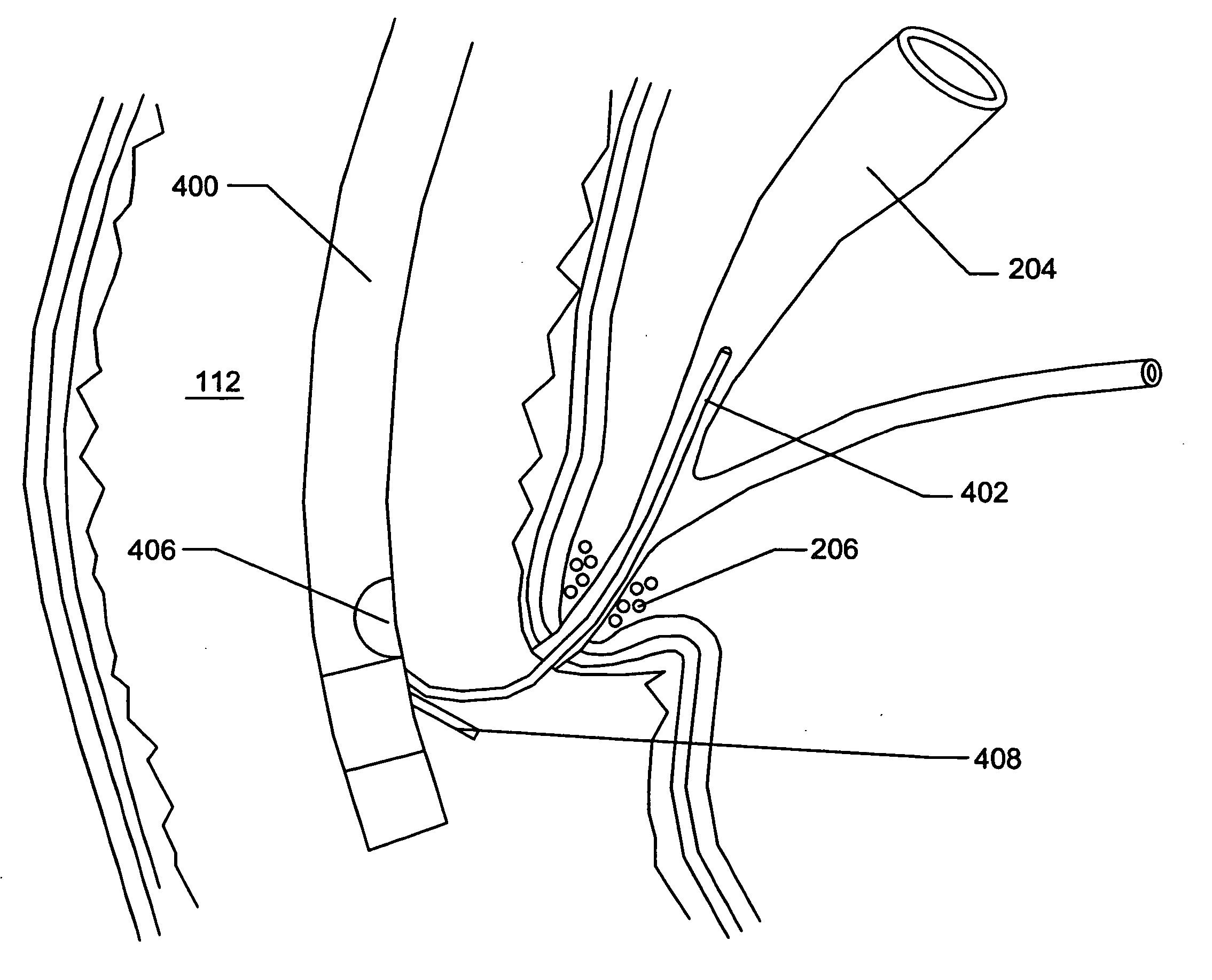
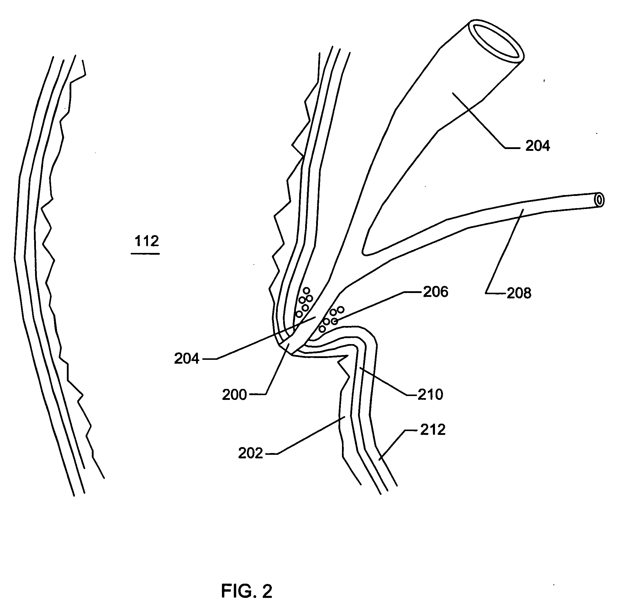
[0024] In another embodiment of the invention, the expandable access sheath is configured to bend, or flex, around sharp corners and be advanced into the
bile duct or
pancreatic duct. Provision can optionally be made to actively orient or steer the sheath through the appropriate angles. The expandable sheath also needs to be able to approach the duct from a variety of positions. Expansion of the distal end of the access sheath from a first smaller diameter cross-section to a second larger diameter cross-section is next performed, using the
balloon dilator. The
balloon dilator is subsequently removed from the sheath to permit passage of instruments that would not normally have been able to be inserted into the bile or
pancreatic duct due to the presence of strictures, stones, or other stenoses of carcinogenic or benign origin. The method further optionally involves releasing the elongate tubular body from a constraining tubular jacket, removing the expandable member from the elongate tubular body; inserting appropriate instrumentation, and performing the therapeutic or diagnostic procedure. Once the sheath is in place, the guidewire may be removed or, preferably, it may be left in place. The
sphincter of hepatopancreatic ampulla is gently dilated with radial force, preferably to a diameter of 10 mm or less, rather than being
cut open by a sphincterotomy procedure or translationally dilated by a tapered dilator or obturator. In one embodiment, the use of the expandable GI sheath eliminates the need for a large diameter right-angle
endoscope in the main
gastrointestinal tract with
resultant benefits in reduced patient discomfort.


