Drilled porous resin base material, and method of manufacturing porous resin base material with conductive drilled inner wall surface

Inactive Publication Date: 2006-06-29
SUMITOMO ELECTRIC IND LTD
View PDF15 Cites 25 Cited by
  • Summary
  • Abstract
  • Description
  • Claims
  • Application Information

AI Technical Summary

Benefits of technology

[0029] A porous resin material having electrically insulating property, a low dielectric constant and elasticity is suitable for use as a resin base of materials for connection between circuits, anisotropically conductive materials or the like. In order to use a porous resin base to pro

Problems solved by technology

When a porous resin material (hereinafter referred to as “porous resin base”) formed in the shape of a substrate is perforated by a machine-working method, however, the base itself is deformed, the porous structure of edges and inner wall surfaces of perforations is collapsed, and burr occurs on opening portions of the perforations, so that it is extremely difficult to form perforations with high precision while retaining the porous structure.
Even when the method of perforating by ultrasonically vibrating the tip of a tool is applied to the porous resin base, it is difficult to form perforations with high precision.
However, this method is unsuitable for a method for perforating a porous resin base composed of a corrosion-resistant resin.
However, it takes a long time to work it, and so the cost thereof is expensive.
When the porous structure of edges and inner wall surfaces of the perforations in the porous resin base is collapsed, the properties characteristic of the porous resin material are impaired.
When the porous structure about the perforations is collapsed, however, the perforated portions are collapsed by only applying a compressive load to the porous resin base once to lose the elasticity.
When the porous structure about the perforated portions is collapsed, however, it is difficult to apply a plating catalyst.
In addition, when the porous structure about the perforated portions is collapsed, the elasticity of the conductive portions is impaired even when the inner wall surfaces of the perforations are made conductive, so that the conductive portions themselves are collapsed when a compressive load is applied.
Further, even when the porous resin base is perforated, it is extremely difficult to selectively apply a conductive metal only to the inner wall surfaces of the perforations by a subsequent secondary working to make them conductive.
As described above, it is difficult to precisely perforate the porous resin base, and the secondary working subsequent to the perforating is also difficult.
However, this method is expensive in working cost.
The anisotropically conductive sheets, in which an elastomer with the conductive particles d

Method used


Image

  • Drilled porous resin base material, and method of manufacturing porous resin base material with conductive drilled inner wall surface
  • Drilled porous resin base material, and method of manufacturing porous resin base material with conductive drilled inner wall surface
  • Drilled porous resin base material, and method of manufacturing porous resin base material with conductive drilled inner wall surface

Examples


Example

Example 1

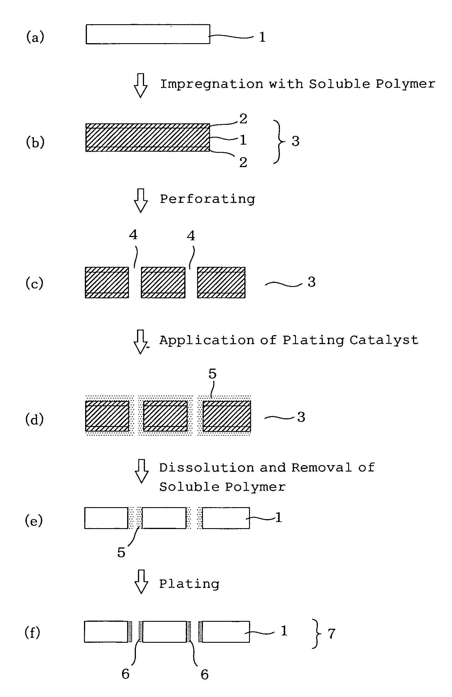
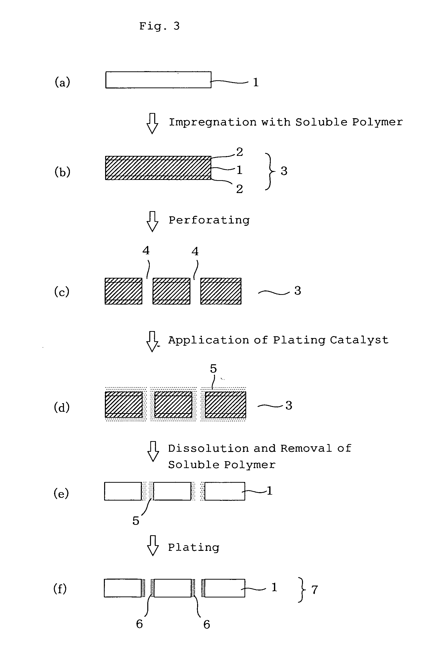
[0214] A porous PTFE base having an area of 10 cm2, a porosity of 60%, an average pore diameter of 0.1 μm and a thickness of 0.5 mm was provided. This porous PTFE base is an expanded PTFE sheet produced by an expanding process and having a microstructure comprising fibrils and nodes connected to each other by the fibrils.

[0215] After the expanded PTFE sheet was dipped in ethanol to subject it to a hydrophilization treatment, the thus-treated sheet was impregnated with water and cooled to 0° C. or lower to solidify water. The expanded PTFE sheet with the solidified water filled into the porous structure thereof was perforated by means of a combination of a punch and a die, which forms through-holes having a diameter of 250 μm. A perforating rate was 100 holes / min. After the perforating, the temperature of the sheet was returned to ordinary temperature, and water was removed by drying.

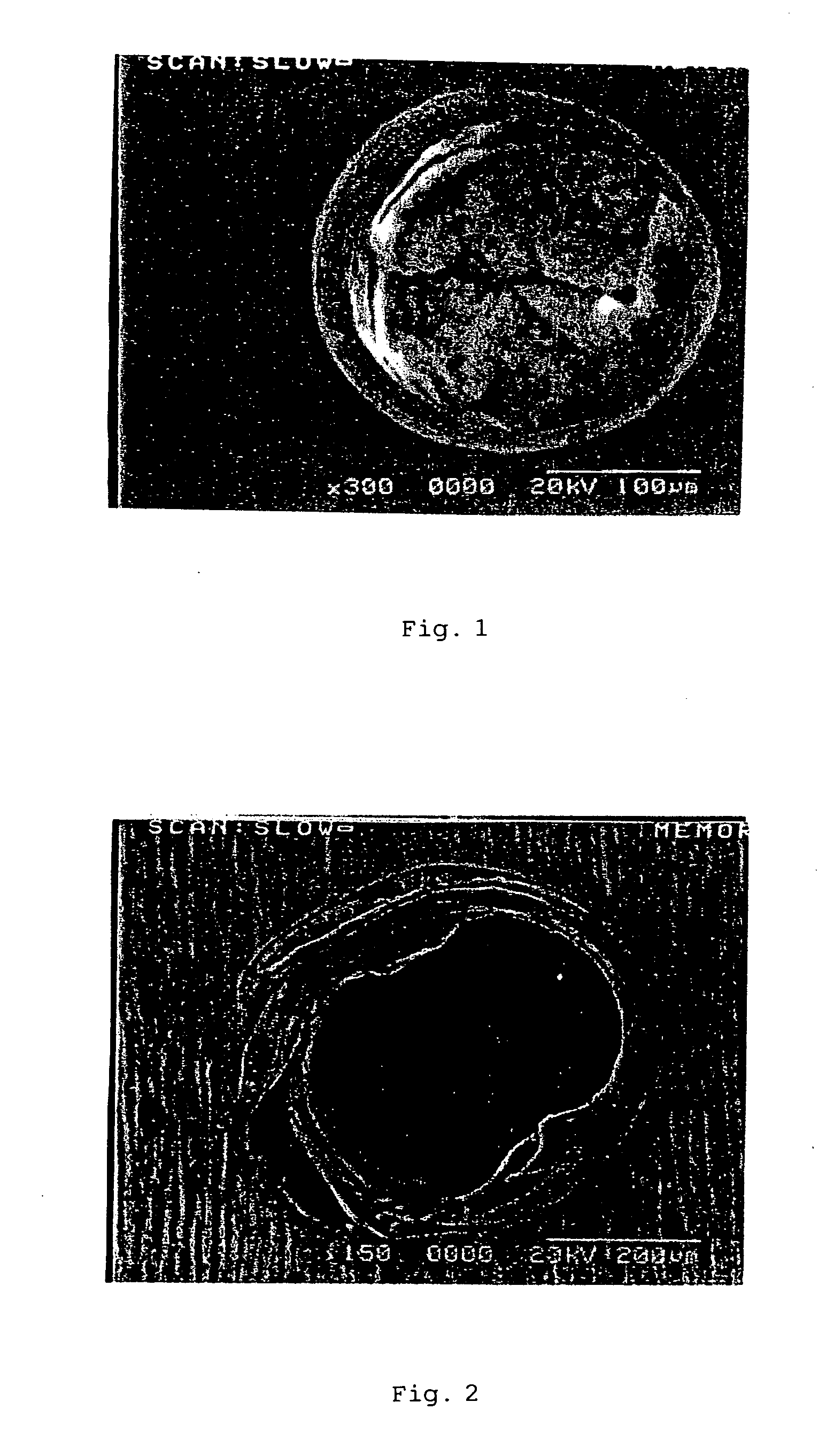
[0216] A perforated portion of the perforated sheet was observed through a microscope. As...

Example

Example 2

[0217] After the same expanded PTFE sheet as that used in Example 1 was provided, impregnated with water and cooled to a temperature not higher than the solidifying point of water, the sheet was perforated by means of a blanking blade produced in such a manner that the diameter of through-holes formed is 1 mm. A perforating rate was 100 through-holes / 4 minutes. After the perforating, the temperature of the sheet was returned to ordinary temperature, and water was removed by drying. A perforated portion of the perforated sheet was then observed. As a result, neither deformation nor burr was observed at peripheries of the perforations like Example 1, and the microstructure of the peripheries of the perforations also retained the same form as other portions than the perforated portions.

Example

Example 3

[0218] After the same expanded PTFE sheet as that used in Example 1 was provided, impregnated with water and cooled to a temperature not higher than the solidifying point of water, the sheet was perforated by means of a drill controlled in such a manner that the diameter of through-holes formed is 250 μm. At this time, the number of revolutions of the drill was 100,000 rpm. A perforating rate was 100 through-holes / 2 minutes. After the perforating, the temperature of the sheet was returned to ordinary temperature, and water was removed by drying. A perforated portion of the perforated sheet was then observed. As a result, no burr was observed at peripheries of the perforations like Example 1, and no collapse of the periphery of the perforated portion was also observed.


PUM

PropertyMeasurementUnit
Temperatureaaaaaaaaaa
Melting pointaaaaaaaaaa

Abstract

A production process of a perforated porous resin base, comprising Step 1 of impregnating the porous structure of a porous resin base with a liquid or solution; Step 2 of forming a solid substance from the liquid or solution impregnated; Step 3 of forming a plurality of perforations extending through from the first surface of the porous resin base having the solid substance within the porous structure to the second surface in the porous resin base; and Step 4 of melting or dissolving the solid substance to remove it from the interior of the porous structure, and a production process of a porous resin base with the inner wall surfaces of the perforations made conductive, comprising the step of selectively applying a catalyst only to the inner wall surfaces of the perforations to apply a conductive metal to the inner wall surfaces.

Description

TECHNICAL FIELD [0001] The present invention relates to a production process of a porous resin base (hereinafter may also be referred to as “porous synthetic resin base”) perforated through the thickness of a porous resin material. The present invention also relates to a production process of a porous resin base with the inner wall surfaces of the perforations selectively made conductive. [0002] The perforated porous resin base obtained by the production process according to the present invention can be utilized in a wide variety of fields of, for example, materials for connection between circuits, anisotropically conductive materials and insulating materials in an electronic field; medical devices such as patch repairing materials in a medical field; and separation membranes. [0003] The porous resin base with the inner wall surfaces of the perforations made conductive, which is obtained by the production process according to the present invention, can be used in, for example, elect...

Claims


Application Information

Patent Timeline
IPC IPC(8): B05D1/40H05K3/42
CPCB29C44/5618B29C67/202H05K3/0011H05K3/0055H05K3/422Y10T29/49167H05K2201/0116H05K2201/015H05K2203/0565H05K2203/0769H05K2203/1147H05K3/426B23B35/00H01L21/02
Inventor OKUDA, YASUHIROHAYASHI, FUMIHIROHAGA, TSUYOSHIFUJITA, TAROUENOYAMA, MAYOMASUDA, YASUHITOIDOMOTO, YUICHI
Owner SUMITOMO ELECTRIC IND LTD
Why Eureka
Try Eureka