High-efficiency, monolithic, multi-bandgap, tandem photovoltaic energy converters

a photovoltaic and solar energy converter technology, applied in the field of monolithic, multi-bandgap, tandem photovoltaic solar energy converters, can solve the problems of reducing energy conversion efficiency, inefficiency and energy loss of unwanted heat, and knowledge alone cannot solve the problem of making efficient and useful energy conversion devices, and achieves high efficiency, flexibility, and special usefulness. , the effect of avoiding defects in lattice-mismatched layers

Active Publication Date: 2006-07-06
ALLIANCE FOR SUSTAINABLE ENERGY
View PDF42 Cites 435 Cited by
  • Summary
  • Abstract
  • Description
  • Claims
  • Application Information

AI Technical Summary

Benefits of technology

[0015] Since lattice-matched subcells are less likely to have defects than lattice-mismatched subcells, and since most of the power is generated by the subcells with bandgaps in the medium and high portions of the solar spectrum, it is preferred that the subcells with bandgaps in the medium and high portions of the solar spectrum be lattice-matched. Also, the substrate can be removed to leave an ultra-thin, monolithic, multi-bandgap, tandem solar photovoltaic converter, which, when mounted on an appropriate handle, can provide superior thermal management, flexibility, particular usefulness and adaptability for monolithic, integrated module (MIM) applications, and the like.
[0016] Bifacial versions can further isolate the lattice-matched subcells from the lattice-mismatched subcells and thereby avoid defects in the lattice-mismatched layers from looping back into the lattice-matched layers. Therefore, in bifacial structures, it is preferred to grow the lattice-matched subcells on one face of the substrate and to grow the graded layer(s) and lattice-mismatched layer(s) on the opposite face.

Problems solved by technology

However, since solar radiation usually comprises a wide range of wavelengths, use of only one semiconductor material with one bandgap to absorb such radiant energy and convert it to electrical energy will result in large inefficiencies and energy losses to unwanted heat.
Semiconductor compounds and alloys with bandgaps in the various desired energy ranges are known, but that knowledge alone does not solve the problem of making an efficient and useful energy conversion device.
Defects in crystalline semiconductor materials, such as impurities, dislocations, and fractures provide unwanted recombination sites for photo-generated electron-hole pairs, resulting in decreased energy conversion efficiency.
Lattice-mismatching (LMM) in adjacent crystal materials causes lattice strain, which, when high enough, is usually manifested in dislocations, fractures, wafer bowing, and other problems that degrade or destroy electrical characteristics and capabilities of the device.
Unfortunately, the semiconductor materials that have the desired bandgaps for absorption and conversion of radiant energy in some energy or wavelength bands do not always lattice match other semiconductor materials with other desired bandgaps for absorption and conversion of radiant energy in other energy or wavelength bands.
Therefore, prior to this invention, ultra-high-efficiency, monolithic, multi-bandgap, tandem, solar photovoltaic (SPV) converters have not been demonstrated due to the lack of a suitable, high-performance, optimum, low-bandgap subcell option to combine with the medium to high bandgap cells in such structures.

Method used


Image

  • High-efficiency, monolithic, multi-bandgap, tandem photovoltaic energy converters
  • High-efficiency, monolithic, multi-bandgap, tandem photovoltaic energy converters
  • High-efficiency, monolithic, multi-bandgap, tandem photovoltaic energy converters

Examples


examples

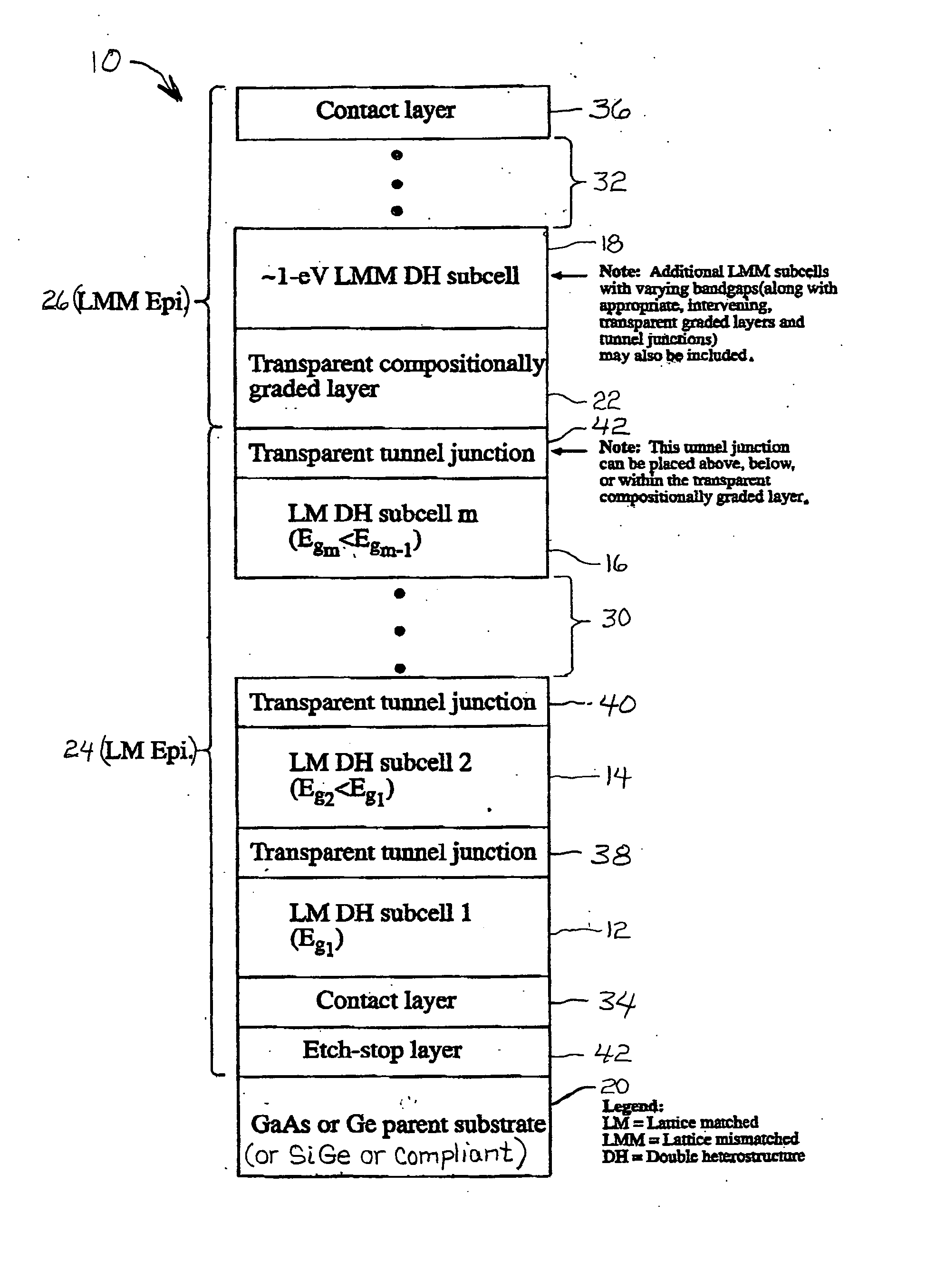
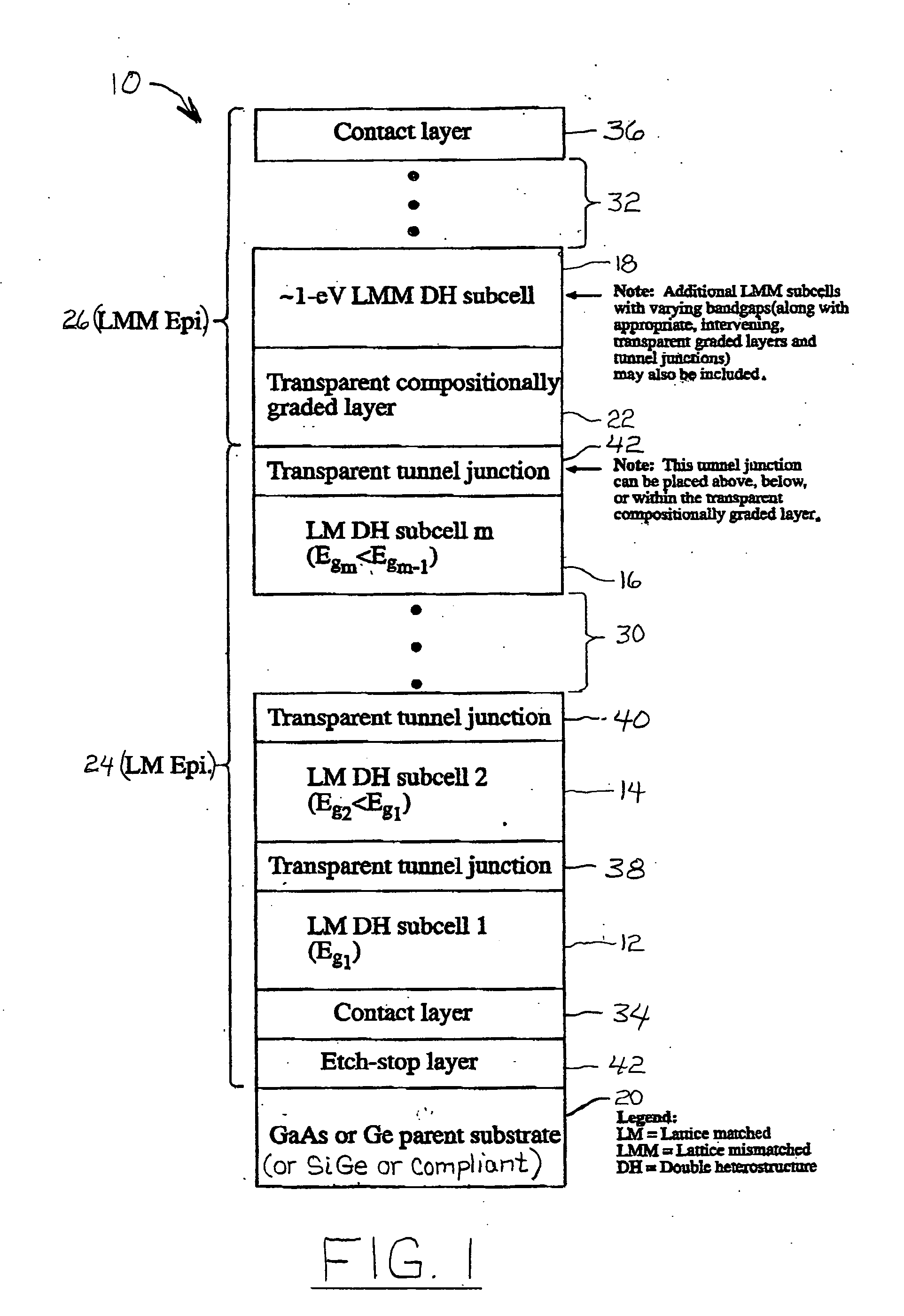
[0064] A series-connected, three-subcell device was grown on a GaAs substrate. LM n-GaInP {(1 μm) etch-stop and n-GaAs (0.4 μm) contact layers were grown first. A LM DH top subcell comprising an n-AlInP (25 nm) front-surface confinement layer (FSCL), n-GaInP (0.1 μm, ordered) emitter layer, p-GaInP (1.2 μm, ordered) base layer, and a p-GaInP (0.1 μm, disordered) back-surface confinement layer (BSCL) was then deposited, followed by a p+ / n+ GaAs tunnel junction (24 nm total thickness). The LM middle subcell comprises a n-GaInP (0.1 μm) emitter layer, a p-GaAs (2.5 μm) base layer, and a p-GaInP (50 nm, ordered) BSCL, followed by another p+ / n+ GaAs tunnel junction (24 nm total thickness). A transparent, compositionally step-graded GaInP layer was then grown to affect a change in lattice constant to match that of the low bandgap (˜1 eV) GaInAs alloy (Ga mole fraction of 0.75, LMM ˜2.2%). The step grade included nine compositional steps with a Ga mole fraction increment of 0.03 per step, ...


PUM


Abstract

A monolithic, multi-bandgap, tandem solar photovoltaic converter has at least one, and preferably at least two, subcells grown lattice-matched on a substrate with a bandgap in medium to high energy portions of the solar spectrum and at least one subcell grown lattice-mismatched to the substrate with a bandgap in the low energy portion of the solar spectrum, for example, about 1 eV.

Description

CROSS-REFERENCE TO RELATED APPLICATIONS [0001] This application is a continuation-in-part of U.S. patent application, Ser. No. 10 / 515,243, entitled “Low-Bandgap, Monolithic, Multi-Bandgap, Optoelectronic Devices,” filed on Nov. 19, 2004, which is incorporated herein by reference for all that it discloses.CONTRACTUAL ORIGIN OF THE INVENTION [0002] The United States Government has rights in this invention under Contract No. DE-AC36-99GO10337 between the United States Department of Energy and the National Renewable Energy Laboratory, a Division of the Midwest Research Institute.TECHNICAL FIELD [0003] This invention is related to photovoltaic devices and, more specifically, to monolithic, multi-bandgap, tandem photovoltaic solar energy converters. BACKGROUND OF THE INVENTION [0004] It is well-known that the most efficient conversion of solar energy to electrical energy with the least thermalization loss in semiconductor materials is accomplished by matching the photon energy of the inci...

Claims


Application Information

Patent Timeline
Patent Type & Authority Applications(United States)
IPC IPC(8): H01L31/00H01L31/042
CPCH01L31/06875H01L31/046Y02E10/544H01L31/0687H01L31/043H01L31/0475
Inventor WANLASS, MARK W.
Owner ALLIANCE FOR SUSTAINABLE ENERGY
Why Eureka
Try Eureka