Cooling electronics via two-phase tangential jet impingement in a semi-toroidal channel

a technology of semi-toroidal channel and tangential jet, which is applied in the direction of indirect heat exchangers, lighting and heating apparatus, domestic cooling apparatus, etc., can solve the problems of limiting the practical approach in most cases to boiling heat transfer, poor choice of air for any type of circulation, and inability to consider the use of refrigerant for high flux needs. , to achieve the effect of increasing the heat flux removal ra

Inactive Publication Date: 2006-07-27
HOANG TRIEM T +1
View PDF11 Cites 62 Cited by
  • Summary
  • Abstract
  • Description
  • Claims
  • Application Information

AI Technical Summary

Problems solved by technology

Air is a poor choice for any type of circulation because of its low mass and low thermal conductivity.
Natural convection with water reaches only about 0.1 W / cm2-C, so this process cannot be considered for use with a refrigerant for high flux needs.
In single-phase flow, water would require a temperature difference of 100C to carry away 1 kW / cm2, limiting the practical approach in most cases to boiling heat transfer.
Drawbacks include the limitations of the minimum size of the hydraulic diameter necessary to avoid flow clogging, and high streamwise pressure drops that can cause flow choking as the fluid suddenly evaporates.
This latter problem limits the size of the cooling device.
Problems here are first the smallness of the effective cooling area and the necessity for very high jet velocities.
There is also a loss in liquid momentum by the orthogonal impact on the plate, and areas of sub-saturated pressure directly under and near the impinging jet that may cause surface bubbles at this region.
A problem with spray cooling is maintenance of the nozzles.
However, the high turbulence quickly causes the liquid film to break up into what is called mist flow, so CHF is exceeded and the heat transfer coefficient falls back sharply.
However, the perpendicular impact will cause momentum and velocity loss in the liquid stream as it turns a right angle to flow along the curved surface.
Further, the radial velocity of the liquid is highest where it moves away in a direction perpendicular from the jet, so if there is any initial circumferential difference in film thickness there will not be sufficient time for the film to come to even thickness.
The extent of the radial flow is limited because eventually the flow friction overcomes the momentum in the liquid film when the film becomes very thin.
This approach suffers from the same problems described above in spray cooling.
This approach adds to the weight and complexity of the cooling system.
Further, in this design the water passages are filled with liquid, so this arrangement does not produce a thin film liquid flow nor does the single-axis curved surface provide an acceleration of flow.
This does not produce a thin film nor accelerate flow.
This does not create a continuous liquid film, nor does it provide uniform cooling of the devices.
This is not possible since the two phases will be at the same temperature at the entrance to the apparatus.

Method used


Image

  • Cooling electronics via two-phase tangential jet impingement in a semi-toroidal channel
  • Cooling electronics via two-phase tangential jet impingement in a semi-toroidal channel
  • Cooling electronics via two-phase tangential jet impingement in a semi-toroidal channel

Examples


Embodiment Construction

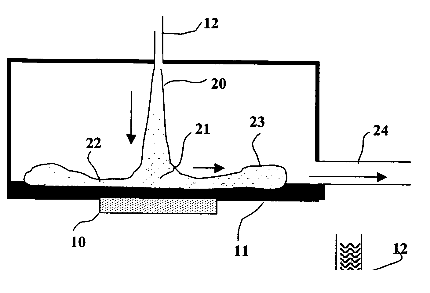
[0035] The present invention is designed to use a two-phase cooling fluid to remove high heat flux from electronics systems over a surface area that is relatively large compared with state-of-art cooling systems. Electronic system designers are now seeking cooling system for thermal fluxes greater than 1 kW / cm2 over areas of tens of square centimeters. Thermal research shows the highest heat removal rate is achieved by a two-phase fluid system wherein heat dissipating devices mounted on a conductive plate evaporate a liquid directed against the opposite side of the plate. The highest flux rates are achieved with water. However, in some cases, e.g., when the system must be dormant in freezing temperatures, it is necessary to use a volatile fluid referred to as a refrigerant (although the operating temperature of the system may be above that normally thought of as refrigeration).

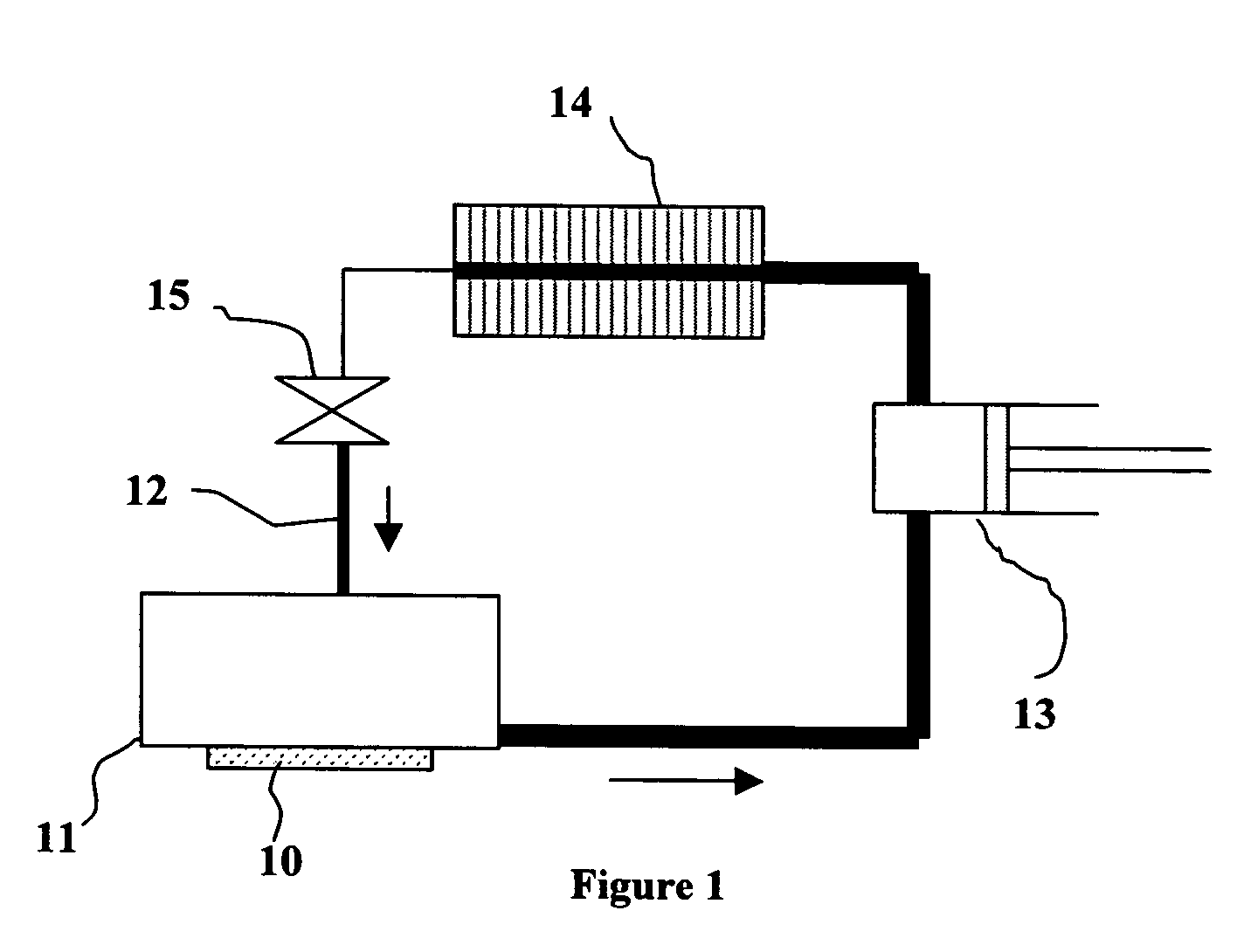
[0036]FIG. 1 is a schematic of a conventional refrigeration cycle as shown in textbooks on thermodynamics....


PUM


Abstract

A two-fluid-phase cooling device for absorbing high thermal flux from electronics devices and other thermally dissipating devices. It consists of a thermally conductive plate with thermally dissipating elements on one face and a semi-toroidal cavity in the opposite face with the cavity's axis perpendicular to the face of the plate, a liquid refrigerant supply tube ending in a thermodynamic cycle's refrigeration expansion valve that directs jets of liquid to impact the conical surface in the center region of the semi-toroidal cavity in a direction along the cavity's axis and tangent to the conical surface, a second plate with a semi-toroidal protrusion extending into the semi-toroidal cavity to form a thin, semi-toroidal channel between the two plates, and a seal between the liquid supply tube and the second semi-toroidal plate. In operation liquid refrigerant jets strike the conical surface generally tangential to the surface and flow at high velocity in a thin film on the surface of the semi-toroidal cavity from its center radially to the outer edge of the toroidal channel, absorbing heat and boiling as it does so. The high radial acceleration forces caused by the liquid film moving at high velocity on the cavity's concave surface force the liquid film against the surface and create a pressure gradient that biases evaporation toward the liquid / vapor interface. The vapor moves parallel to the liquid flow radially outwards between the liquid film and the surface of the semi-toroidal protrusion at very high velocity, causing extreme turbulence in the liquid film and highly augmented heat transfer between the heated plate and the liquid film, while the liquid film nevertheless remains intact and forced against the heated surface by radial acceleration and carried to a distance significantly greater than in conventional jet impingement systems. The device may also be composed of wedge-shaped sections of the semi-toroidal plates. It may further have two expansion valves in series in the liquid supply line, the first generating a small amount of vapor (increase in quality) so the resulting increase in flow volume greatly increases the velocity through the second expansion valve toward the heated surface to further enhance heat transfer.

Description

CROSS-REFERENCE TO RELATED APPLICATIONS [0001] This application claims the benefit of provisional patent application Ser. No. 60 / 621,894, filed 2004 Oct. 22 by the present inventors.FEDERALLY SPONSORED RESEARCH [0002] Not Applicable SEQUENCE LISTING OF PROGRAM [0003] Not Applicable BACKGROUND OF THE INVENTION [0004] 1. Field of Invention [0005] This invention relates to cooling electronics, specifically to spray-cooling of two-phase fluid on a heated surface contained within a conventional refrigeration loop. [0006] 2. Prior Art [0007] The problem addressed in this invention is removal of high thermal dissipation flux from electronic devices such as amplifier gate arrays, laser diodes, etc. [0008] Heat flux from electronics is now in the range of 100 to 1,000 Watts per square centimeter (W / cm2). Thermal literature refers to this as the high-flux range, and ultra-high flux being from 103 to 105 W / cm2 and describes a number of ways to remove the heat. If the heated surface is in the i...

Claims


Application Information

Patent Timeline
Patent Type & Authority Applications(United States)
IPC IPC(8): F25D23/12F28D5/00
CPCF25B39/02F25B2339/021H01L23/4735H01L2924/0002H01L2924/00
Inventor HOANG, TRIEM T.BROWN, MICHAEL ANTHONY
Owner HOANG TRIEM T
Why Eureka
Try Eureka