Semiconductor device and method for manufacturing the same, and electric device

a technology of semiconductor devices and semiconductors, applied in the field of semiconductor devices, can solve the problems of complex process and high target cost, and achieve the effect of high circuit integration and simplified steps

Inactive Publication Date: 2006-07-27
SEMICON ENERGY LAB CO LTD
View PDF38 Cites 127 Cited by
  • Summary
  • Abstract
  • Description
  • Claims
  • Application Information

AI Technical Summary

Benefits of technology

[0019] It is an object of the present invention to simplify steps needed to process a wiring in forming a multilayer wiring. Further, it is an object of the present invention to provide a technique to realize high integration of a circuit.
[0020] In addition, in the case of forming a plurality of contact holes different in depth, a process tends to be complicated. Consequently, the present invention provides a technique capable of realizing a plurality of contact holes different in depth in a simplified process.

Problems solved by technology

In addition, in the case of forming a plurality of contact holes different in depth, a process tends to be complicated.
In forming a metal film to be a wiring by a deposition method with the use of a sputtering method when the substrate size is further increased hereafter, a target becomes expensive as the size is increased, which is disadvantageous for mass production.

Method used


Image

  • Semiconductor device and method for manufacturing the same, and electric device
  • Semiconductor device and method for manufacturing the same, and electric device
  • Semiconductor device and method for manufacturing the same, and electric device

Examples


embodiment mode 1

[0097] In this embodiment mode, a method for forming a contact hole in a first conductive layer and a method for forming a second conductive layer electrically connected to the first conductive layer through the contact hole will be explained with reference to FIGS. 1A to 1D, FIGS. 2A and 2B, FIG. 10, and FIG. 11.

[0098] First, a base insulating film 11 is formed over a substrate 10 having an insulating surface, and a first conductive layer 12 is formed over the base insulating film 11. Next, an insulating film 13 covering the first conductive layer 12 is formed. A cross-sectional view of this stage is shown in FIG. 1A.

[0099] Note that a glass substrate or quartz substrate having light transparency is preferably used as the substrate 10 having an insulating surface.

[0100] In addition, as for the base insulating film 11, a base film made of an insulating film such as a silicon oxide film, a silicon nitride film, or a silicon oxynitride film is formed. Herein, an example where a two...

embodiment mode 2

[0126] In this embodiment mode, an example of an opening the cross-sectional shape of which differs from Embodiment Mode 1 will be shown with reference to FIGS. 3A to 3C. Portions different from Embodiment Mode 1 will be explained in detail and portions identical with FIGS. 1A to 1D in FIGS. 3A to 3C are denoted by the same reference numerals.

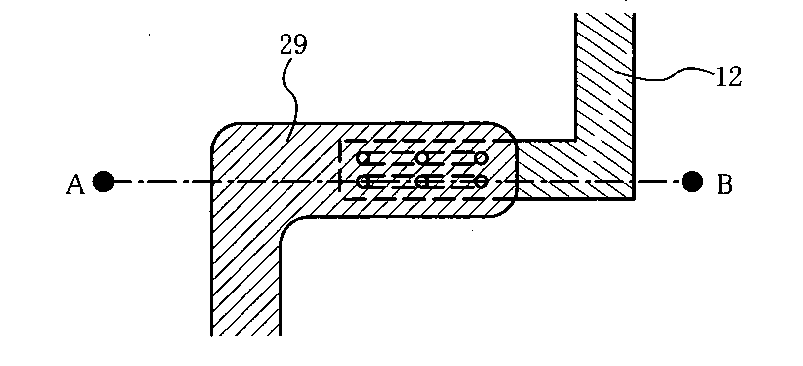
[0127] Note that a cross-sectional shape of an opening in FIGS. 1A to 1D is shown in a columnar shape; however, the present invention is not limited thereto and an opening the shape of which has a structure in which a plurality of openings is connected to each other in an insulating film as shown in FIG. 3 may be employed.

[0128] First, as well as in Embodiment Mode 1, a base insulating film 11 and a first conductive layer 12 are formed over a substrate 10 having an insulating surface.

[0129] Next, after forming an insulating film made of a material that is light transmitting to laser light having a pulse width of 10−4 seconds to 10−2 seconds,...

embodiment mode 3

[0140] In this embodiment mode, an example of forming a plurality of openings with the combination of laser light and etching will be explained with reference to FIGS. 4A to 4C. Portions different from Embodiment Mode 1 will be explained in detail, and portions identical with FIGS. 1A to 1D are denoted by the same reference numerals in FIGS. 4A to 4C.

[0141] After forming an insulating film made of a material that is light transmitting to laser light having a pulse width of 10−4 seconds to 10−2 seconds, an insulating film 33 having a closed pore 37 is obtained by irradiation of ultrashort pulsed laser light. When an ultrashort pulsed laser is condensed in the insulating film, multiphoton absorption can occur only at a condensed spot where the ultrashort pulsed laser is condensed, a closed pore can be formed, and one penetrating opening can be formed by moving the condensed spot. When the pulsed width of the laser light is 10−4 seconds to 10−2 seconds, the laser light is not absorbed...


PUM

PropertyMeasurementUnit
diameteraaaaaaaaaa
diameteraaaaaaaaaa
repetition frequencyaaaaaaaaaa

Abstract

It is an object of the present invention to simplify steps needed to process a wiring in forming a multilayer wiring. In addition, when a droplet discharging technique or a nanoimprint technique is used to form a wiring in a contact hole having a comparatively long diameter, the wiring in accordance with the shape of the contact hole is formed, and the wiring portion of the contact hole is likely to have a depression compared with other portions. A penetrating opening is formed by irradiating a light-transmitting insulating film with laser light having high intensity and a pulse high in repetition frequency. A plurality of openings having a minute contact area is provided instead of forming one penetrating opening having a large contact area to have an even thickness of a wiring by reducing a partial depression and also to ensure contact resistance.

Description

BACKGROUND OF THE INVENTION [0001] 1. Field of the Invention [0002] The present invention relates to a semiconductor device having a circuit including a thin film transistor (hereinafter, referred to as a TFT) and to a manufacturing method thereof. Specifically, the present invention relates to a semiconductor device having a circuit including a field effect transistor (hereinafter, referred to as an FET). For example, the present invention relates to an electronic device incorporating, as part thereof, a large-scale integrated circuit (LSI), an electro-optic device typified by a liquid crystal display panel, a light-emitting display device having an organic light-emitting element, a sensor device such as a line sensor, or a memory device such as an SRAM or a DRAM, for example. [0003] 2. Description of the Related Art [0004] Note that a semiconductor device in this specification means general devices and apparatuses that can function with the use of semiconductor characteristics; fo...

Claims


Application Information

Patent Timeline
Patent Type & Authority Applications(United States)
IPC IPC(8): G03C5/00H01L21/4763H01L23/48H05B44/00
CPCG02F1/136227H01L21/288H01L2924/0002H01L21/76802H01L21/76816H01L21/76838H01L21/76877H01L23/49855H01L23/5226H01L29/41733H01L2924/12044H01L27/124H01L27/1285H01L27/1292H01L2924/00
Inventor KUWABARA, HIDEAKIYAMAMOTO, HIROKO
Owner SEMICON ENERGY LAB CO LTD
Why Eureka
Try Eureka