Fiber-reinforced composite material, method for manufacturing the same and applications thereof

a composite material and fiber reinforcement technology, applied in the direction of dielectric characteristics, instruments, cellulosic plastic layered products, etc., can solve the problems of degradation of transparency of composite materials, disaggregated cellulose, and inability to obtain transparency, etc., to achieve superior transparency, superior flexural strength and flexural modulus, and superior transparency

Active Publication Date: 2006-08-17
MITSUBISHI CHEM CORP +2
View PDF16 Cites 60 Cited by
  • Summary
  • Abstract
  • Description
  • Claims
  • Application Information

AI Technical Summary

Benefits of technology

[0014] A second object of the present invention is to provide a transparent multilayered sheet having a transparent conductive layer, the transparent multilayered sheet being capable of always maintaining superior transparency without being influenced by temperature conditions, wavelengths and the like, having a light weight, causing no damage done to the transparent conductive film due to the difference in coefficient of linear thermal expansion between a base material and the transparent conductive film and no degradation in conductivity caused by the above damage, and being capable of withstanding a repeatedly applied stress and the like so as not to cause any breakage problem.
[0033] Since having high flexural strength and flexural modulus, the base material made of the fiber-reinforced composite material is hardly deformed or broken by a mechanical stress applied thereto. Hence, damage done to the transparent conductive film caused by deformation of the base material can be prevented, and decrease in electrical conductivity or disappearance thereof caused by the above damage can also be prevented.

Problems solved by technology

The refractive index of each material has its own wavelength dependence; hence, even when the refractive index of fibers and that of a matrix resin are allowed to coincide with each other at a specific visible light wavelength, a region in which the refractive index is shifted may probably exist in the entire visible light region, and as a result, in the region described above, the transparency cannot be obtained.
When a product produced by bacteria is disaggregated by applying a mechanical shearing force by a grinder or the like, bacterial cellulose fibers are closely attached to each other during a disaggregation process to form bundles having a large fiber diameter which may cause refraction and scattering of visible light, resulting in degradation in transparency of a composite material formed using the disaggregated cellulose as described above.
As described above, as of today, there has not been provided a fiber-reinforced composite material that always maintains superior transparency regardless of temperature conditions and wavelength bands.
A glass plate is heavy and has an inferior impact resistance.
Although being lighter in weight than a glass plate, a resin sheet has the following problems.
In this case, when the difference in coefficient of linear thermal expansion between the base material and the transparent conductive film is large, by a stress generated at the interface therebetween, damages, such as cracking and peeling, may be done to the transparent conductive film, and as a result, the conductivity may be degraded in some cases by the damages done to the transparent conductive film.
When the traveling contact support plate has insufficient flexural strength and / or flexural modulus, the support plate may be deformed or broken by a pressing force repeatedly applied to the plate in operation.
Also in this case, the conductivity is degraded due to the degradation of the transparent conductive film.

Method used


Image

  • Fiber-reinforced composite material, method for manufacturing the same and applications thereof
  • Fiber-reinforced composite material, method for manufacturing the same and applications thereof
  • Fiber-reinforced composite material, method for manufacturing the same and applications thereof

Examples


manufacturing example 1

Manufacturing of BC Sheet

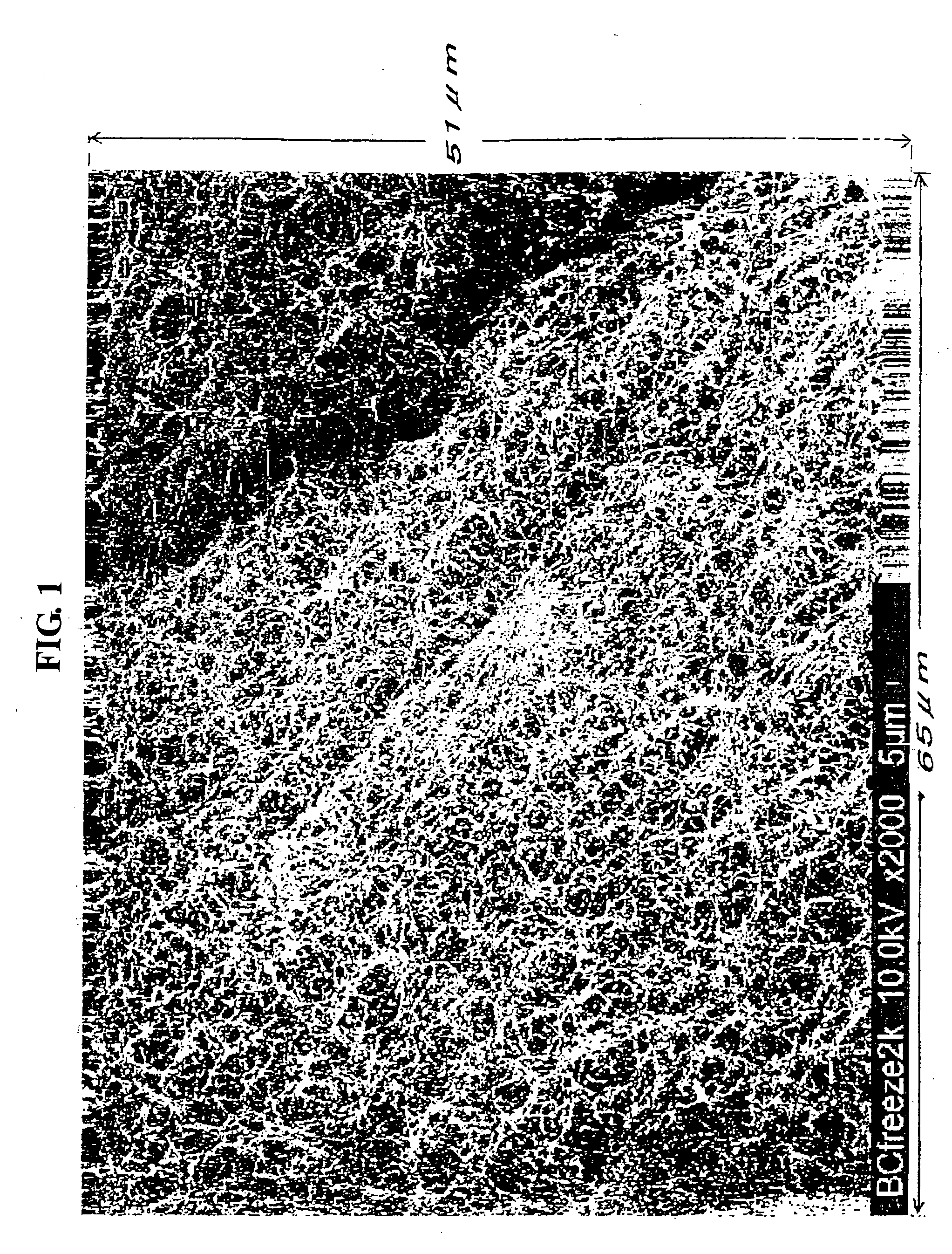
[0238] After a culture fluid was added to a strain of acetic acid bacteria stored in a freeze-dried state, stationary culture was performed for 1 week (25 to 30° C.). On the surface of the culture fluid, bacterial cellulose was produced, and after a relatively thick part of the bacterial cellulose thus produced was selected, a small amount of a culture fluid of that strain was sampled and then added to a new culture fluid. Subsequently, this culture fluid was placed in a large incubator, followed by stationary culture for 7 to 30 days at 25 to 30° C. As the culture fluid, an aqueous solution (SH culture medium) having a pH of 5.0 adjusted by hydrochloric acid was used, containing 2 percent by weight of glucose, 0.5 percent by weight of bactoyeast extract, 0.5 percent by weight of bactopeptone, 0.27 percent by weight of disodium hydrogenphosphate, 0.115 percent by weight of citric acid, and 0.1 percent by weight of magnesium sulfate heptahydrate.

[0239] The ...

example 1

Analysis Example 1

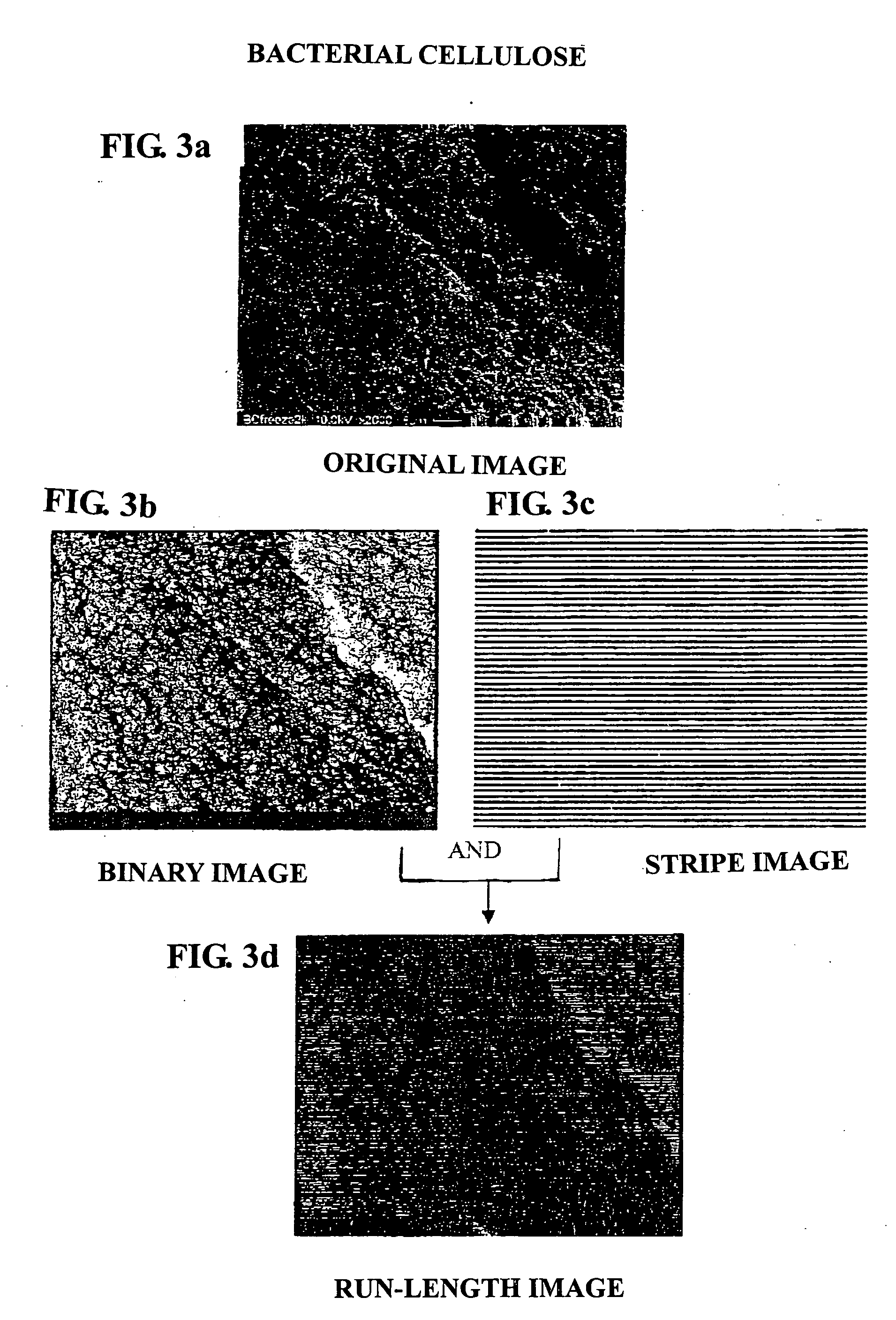
[0243] In accordance with the image analysis method for evaluation of the ≧4.5 μm RL ratio, the ≧4.5 μm RL ratios in the longitudinal and the lateral directions were measured for the bacterial cellulose obtained in manufacturing example 1 and the disaggregated bacterial cellulose obtained in manufacturing example 2.

[0244]FIG. 3a shows an original image of the bacterial cellulose, FIG. 3b shows a binary image of the bacterial cellulose. This binary image was overlapped with a stripe image in FIG. 3c, so that a run-length image shown in FIG. 3d was obtained.

[0245]FIG. 4a shows an original image of the disaggregated bacterial cellulose, FIG. 4b shows a binary image of the disaggregated bacterial cellulose. This binary image was overlapped with a stripe image in FIG. 4c, so that a run-length image shown in FIG. 3d was obtained.

[0246] In the stripe images shown in FIGS. 3c and 4c, for the convenience of illustration in the figure, the line width was shown larger than...

manufacturing example 3

Manufacturing of MFC Sheet

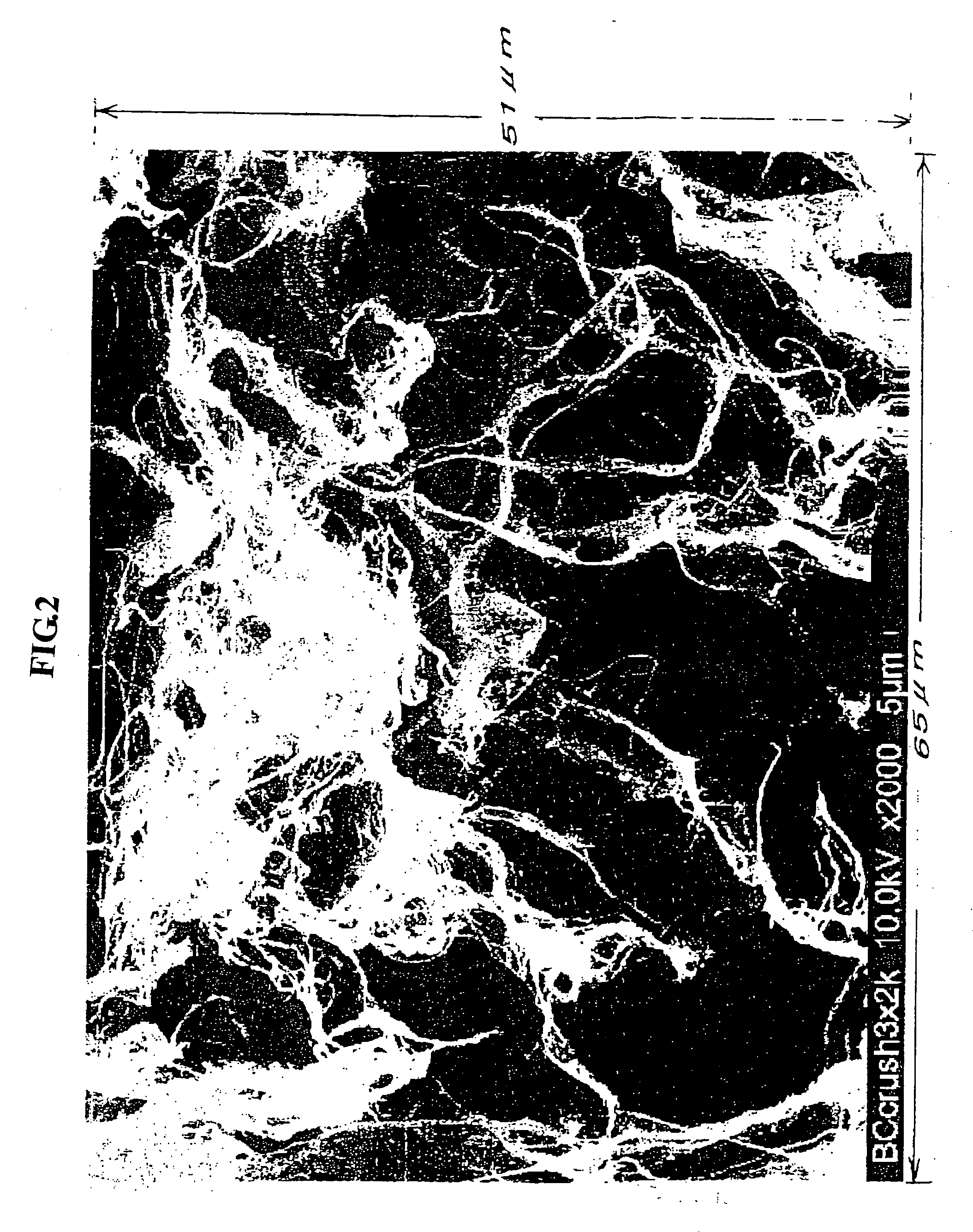
[0250] Microfibrillated cellulose: After MFC (obtained by microfibrillation of nadelholz bleached kraft pulp (NBKP) using a high pressure homogenizer, having an average fiber diameter of 1 μm) was sufficiently stirred with water to prepare 7 kg of an aqueous suspension at a concentration of 1 percent by weight, this aqueous suspension was allowed to repeatedly pass between two rotating discs of a grinder (manufactured under the trade name “Pure Fine Mili KMG1-10” by Kurita Machinery Mfg. Co., Ltd.) from the center to the outside 30 times (30 passes), the two discs being almost in contact with each other and at the disc revolution speed of 120 rpm.

[0251] From Nano MFC (average fiber diameter of 60 nm) obtained by the grinding treatment, an aqueous suspension at a concentration of 0.2 percent by weight was prepared, followed by filtration using a glass filter, and film formation was performed. This film was dried at 55° C., so that a Nano MFC sheet having a...


PUM

PropertyMeasurementUnit
thicknessaaaaaaaaaa
light transmittanceaaaaaaaaaa
thicknessaaaaaaaaaa

Abstract

There is provided a fiber-reinforced composite material containing fibers having an average fiber diameter of 4 to 200 nm and a matrix material, the composite material having a visible light transmittance of 60% or more at a wavelength of 400 to 700 nm, which is a conversion value based on a thickness of 50 μm. A fiber-reinforced composite material composed of a matrix material and a fiber aggregate impregnated therewith is provided, in which when a segment length of a bright region corresponding to a pore region of the fiber aggregate is represented by L, which is obtained by statistical analysis of a unidirectional run-length image formed from a binary image obtained by binarization of a scanning electron microscopic image of the fiber aggregate, the total length of segments that satisfy L≧4.5 μm is 30% or less of the total analyzed length. A transparent multilayered sheet, a circuit board, and an optical waveguide are provided which use a transparent substrate formed from this fiber-reinforced composite material.

Description

CROSS REFERENCE TO RELATED APPLICATION [0001] This is a continuation application of PCT / JP2004 / 010703 filed on Jul. 28, 2004.FIELD OF THE INVENTION [0002] The present invention relates to a fiber-reinforced composite material and a method for manufacturing the same, and also relates to a transparent multilayered sheet, a circuit board, and an optical waveguide, each of which is formed using the above fiber-reinforced composite material. In more particular, the present invention relates to a highly transparent fiber-reinforced composite material composed of a matrix material and fibers impregnated therewith and a method for manufacturing this fiber-reinforced composite material, and also relates to a transparent multilayered sheet, a circuit board, and an optical waveguide, each of which is formed using a substrate composed of this fiber-reinforced composite material. BACKGROUND OF THE INVENTION [0003] As the most general fiber-reinforced composite material, a glass fiber-reinforced ...

Claims


Application Information

Patent Timeline
Patent Type & Authority Applications(United States)
IPC IPC(8): D04H13/00C08J5/00C08J5/04G02B6/10G02B6/12G02B6/122G02B6/42H05K1/03
CPCB82Y30/00Y10T428/2965C08J5/04C08L101/00G02B6/10G02B6/122G02B6/4214G02B2006/12104G02B2006/12107H05K1/0366H05K2201/0108H05K2201/0251C08J5/005C08L2666/26Y10T428/31518Y10T428/24994Y10T428/31525Y10T428/249928Y10T428/249924C08J5/24H05K1/03G02B6/12C08K7/02
Inventor YANO, HIROYUKISUGIYAMA, JUNJINOGI, MASAYAIWAMOTO, SHIN-ICHIROHANDA, KEISHINNAGAI, AKIRAMIWA, TAKAOTAKEZAWA, YOSHITAKAMIYADERA, TOSHIYUKIKURIHARA, TAKASHIMATSUURA, TOHRUKOSHOUBU, NOBUTATSUMARUNO, TOHRU
Owner MITSUBISHI CHEM CORP
Why Eureka
Try Eureka