System,apparatus and method for large area tissue ablation

a tissue ablation and large-area technology, applied in the field of tissue ablation, can solve the problems of inability to achieve significant practical use of devices, inability to generally use lasers clinically, and extreme discomfort of procedures, and achieve the effect of minimizing the shift of an absorption curv

Inactive Publication Date: 2006-08-24
B E D LASER TECH
View PDF28 Cites 55 Cited by
  • Summary
  • Abstract
  • Description
  • Claims
  • Application Information

AI Technical Summary

Benefits of technology

[0034] According to still further features in the described preferred embodiments the at least one scanning-parameter is selected so as to minimize heating of internal layers of the material.
[0035] According to still further features in the described preferred embodiments the at least one scanning-parameter is selected so as to minimize shifts in an absorption curve of at least one component present in the material.
[0073] According to still further features in the described preferred embodiments the scanning assembly is designed and constructed to scan the material in such a manner that heating of internal layers of the material is minimized.

Problems solved by technology

Such procedures are extremely uncomfortable, painful to the patient, and produce results having quite a few drawbacks.
However, lasers have not generally been used clinically until early 90's for surgical processes, including tooth drilling, because of the large amount of damage to nearby tissue that was often associated with such laser drilling.
While a number of devices for dental treatment of this type have been proposed, these devices have not proven to be of practical use notably because even the most effective of these devices are useful only under limited and very precisely defined conditions.
Pulsed lasers and lasers producing infrared radiation have been developed both for soft tissue and bone ablation, and, although were found to be less damaging than other lasers, they still yielded unsatisfactory results.
To achieve this result, however, extremely short laser pulses (on the order of nanoseconds) must be used, and the thickness of the biological material removed by this method is between 10 and 50 μm.
Because hard biological material has a limited heat transfer capacity, however, increasing the repetition rate of the pulses rapidly leads to an accumulation of heat around the zone of removal, and hence leads to thermal damage of the areas peripheral to the treatment area.
A known problem with ablation of hard tissues is that the ablation process saturates after few tens of pulses.
Any absorption of laser radiation by the tissue other than the tissue which is to be ablated causes the undesired effect of saturation.
An additional effect that strongly reduces the ablation efficiency is the so called, debris screening.
Thus, a significant amount of the laser energy is absorbed by tissue which has already been ablated.
This effect causes a dramatic reduction in the ablation efficiency and becomes even more significant with the increase of the laser pulse duration or the laser pulse energy.
In these procedures, nowadays, due to the above identified problems, mechanical drill is typically used.
Each such drill change requires halting the operation for 15-30 seconds, thus considerably increasing the overall operation time and thereby the discomfort to the patient.
In addition, the drilling process is extremely long and uncomfortable.
This technique, however, fail to provide a solution to the problem of over-heating of the irradiated spot due to long pulse duration.
Although ultraviolet lasers vaporize a material target with minimal thermal energy transfer to adjacent tissue, such lasers suffer from a major limitation due to a relatively small active area, which prohibits the use of ultraviolet lasers for ablating large areas of hard tissues.
None of the above documents, however, provide adequate solutions to the problems associated with overheating of the irradiated area due to long pulse duration and / or ablation of large areas of hard tissues.

Method used


Image

  • System,apparatus and method for large area tissue ablation
  • System,apparatus and method for large area tissue ablation
  • System,apparatus and method for large area tissue ablation

Examples


example 1

A Model for Laser-Tissue Interaction

[0213] Theory

[0214] A theoretical model for laser-tissue interaction dynamics has been developed. The model takes into account the non-linearity of the laser absorption coefficient and the non-uniform intensity distribution within the laser pulse.

[0215] The non-linearity range of the absorption coefficient is known to be significant for extremely high applied energies, such as ablation energies.

[0216]FIG. 12 shows results of measurements of absorption coefficient, α, of water as a function of the applied energy density, were the absorption coefficient, α, is presented on a linear scale in units of cm−1 and the energy density is presented on a logarithmic scale in units of J / cm3 [A. Saar, D. Gal, R. Wallach, S. Akselrod, A. Katzir, Appl. Phys. Lett 50, 1556 (1987)]. The non-linearity of the absorption coefficient is vivid.

[0217] Generally, the experimental results, presented in FIG. 12, may be parameterized using the following equation, define...

example 2

Experimental Investigations of Hard Tissue Ablation

[0231] Methods

[0232] An Er:YAG laser was used for ablating hard tissues of freshly extracted human teeth. The goal of the experiments was to study the dynamic of the interaction between a hard tissue and a laser beam.

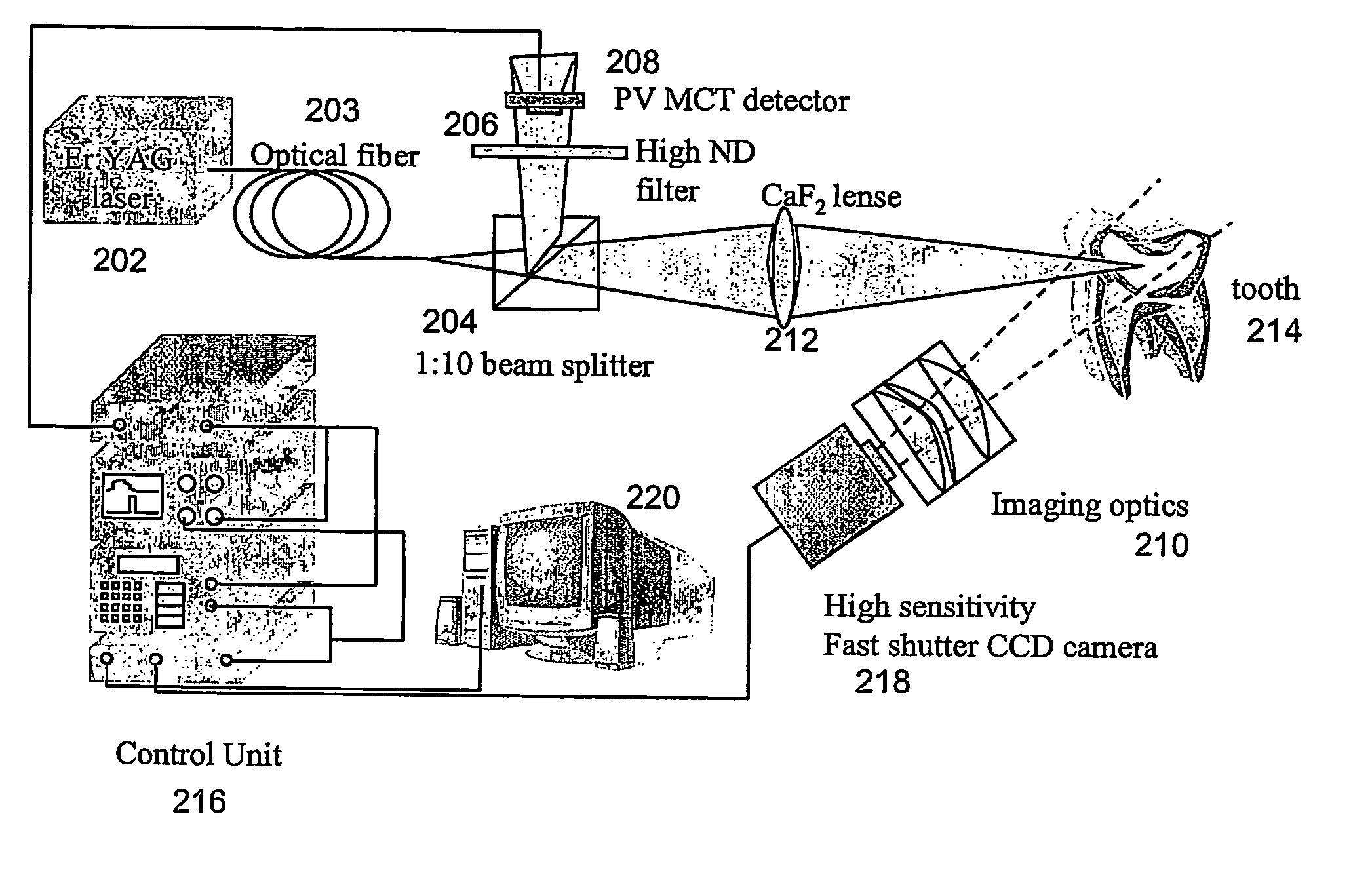
[0233] The experimental system is schematically shown in FIG. 15.

[0234] A beam of laser emitted from an Er:YAG laser 203 was guided by an optical waveguide 203 to a beam splitter 204. Beam splitter 204 directed about 90% of the beam to a CaF2 lens 212 which focused the beam onto tooth 214, while the remaining 10% of the beam was directed through a High ND filter 206 to a detector 208 (photovoltaic Mercury-Cadmium-Telluride) and was used for synchronization. The synchronization was governed by a control unit 216, and a computer 220 was used for collecting data. A sensitive fast CCD camera 218, synchronized with the laser beam was used, together with an arrangement 210 of imaging optical elements for imaging tooth 214...

example 3

Fast Scanning of Hard Tissues

[0238] Methods

[0239] An Er:YAG laser of Example 2, was used for ablating hard tissues of freshly extracted human teeth, employing features of the method of the present invention. The goal of the experiments was to optimize the scanning-parameters and to study the effect thereof on the efficiency and quality of the ablating process.

[0240] The experimental system is schematically shown in FIG. 17. The laser radiation and the synchronization with camera 218 were as further detailed hereinabove in Example 2.

[0241] A scanning assembly, essentially as detailed hereinabove was used for scanning tooth 214 with the laser beam. Two galvanometric actuators 228 were used for dynamically diverting the beam.

[0242] A polished gold mirror 8×8 cm in lateral dimension and 1 mm in thickness was manufactured and integrated on galvanometric actuators 228 so as to achieve a minimal moment of inertia. The resulting bandwidth of the scanning assembly was 1.2 kHz. A scannin...


PUM


Abstract

A method of ablating a material, the method comprising: (a) generating a beam of laser radiation in a form of plurality of pulses, the laser radiation having a wavelength suitable for ablating the material; and (b) within a duration of a pulse of the plurality of pulses, scanning the material by the beam, so as to transfer a predetermined amount of energy to each one of a plurality of locations of the material, the predetermined amount of energy being selected so as to ablate the material.

Description

FIELD AND BACKGROUND OF THE INVENTION [0001] The present invention relates to tissue ablation and, more particularly, to tissue ablation using electromagnetic radiation, e.g., laser radiation. Most particularly, the present invention relates to hard tissue, such as teeth and bones, ablation using laser radiation. The invention present invention also relates to ablations of other materials such as ceramics. [0002] Over the years, light and more specifically laser light has been used for the analysis, treatment, destruction or ablation of tissues. [0003] The introduction of the laser technology in 1960, brought the light to a large variety of applications by producing spatially coherent light having very high intensity. Nowadays, laser technology has found many applications in medicine and biology, mostly in procedures which are related to the treatment of soft tissues. [0004] Lasers are optical devices which produce intense and narrow beams of light at particular wavelengths by stimu...

Claims


Application Information

Patent Timeline
Patent Type & Authority Applications(United States)
IPC IPC(8): A61B18/18A61C3/00A61B19/00A61BA61B18/20A61C1/00A61C13/12
CPCA61B18/20A61B2018/2085A61C1/0046A61C13/12A61B2018/20351A61B2018/20355A61B2018/208
Inventor LITVAK, EMILREGELMAN, DAN V.MEZHERICKY, BORIS
Owner B E D LASER TECH
Why Eureka
Try Eureka