Illumination optical system and projection display optical system

a technology of which is applied in the field of illumination optical system and projection display optical system, can solve the problems of reducing the light amount, affecting the effect of light amount, and complicated optical system, and achieves the effect of suppressing the reduction of light amount and reducing the blockage of light amoun

Inactive Publication Date: 2006-09-14
CANON KK
View PDF8 Cites 43 Cited by
  • Summary
  • Abstract
  • Description
  • Claims
  • Application Information

AI Technical Summary

Benefits of technology

[0023] It is an object of the present invention to provide an illumination optical system which provides an illumination luminous flux with a small incident angle on an illumination surface in one axis direction on a section of the illumination luminous flux and which suppresses a reduction in light amount blocked by a mask (that is, a reduction in light amount) provided for a polarization conversion element, a projection display optical system which employs the illumination optical system, a projection display apparatus, and an image display system.
[0024] To achieve the aforementioned object, according to one aspect, the present invention provides an illumination optical system which has a light source, an optical integrator, and a polarization conversion element including a polarization beam splitter array, a plurality of ½ wave plates, and a mask. The optical integrator uses a lens array to perform splitting (or splitting and recombination) of a luminous flux incident as a generally collimated luminous flux from the light source in a first axis direction in a two-dimensional section orthogonal to a traveling direction of the illumination luminous flux. The polarization beam splitter array has a plurality of polarization beam splitters arranged in multiple stages corresponding to a plurality of predetermined lens areas in the lens array. Each of the ½ wave plates rotates a polarization direction of first polarized light substantially 90 degrees out of the first and second polarized light with polarization directions orthogonal to each other split by each of the polarization beam splitters. The mask covers a plurality of areas of incident surfaces of the polarization beam splitter array to prevent incident of the second polarized light on each of the ½ wave plates.

Problems solved by technology

When the kaleidoscope is used, an optical system is complicated if a means for converting natural emission light from the light source into linearly polarized light is used.
When the light modulation panel is realized by a reflection type liquid crystal display panel or a micromirror array device, limitations are imposed on space for forming an optical path along which the illumination light is guided.
When a polarization beam splitter is used to guide light, limitations are imposed due to dependency of the reflectivity of S waves and transmittance of P waves on the incident angle.
In the illumination optical system described above, however, when an incident luminous flux from a light source lamp has large divergence, the use efficiency of light from the light source may be reduced.
In this case, a disadvantage occurs in the use efficiency of light from the light source lamp.
Consequently, a larger amount of light with divergence from the light source is shielded by the multi-stage slit mask to reduce light transfer efficiency of the illumination optical system.

Method used


Image

  • Illumination optical system and projection display optical system
  • Illumination optical system and projection display optical system
  • Illumination optical system and projection display optical system

Examples


embodiment 1

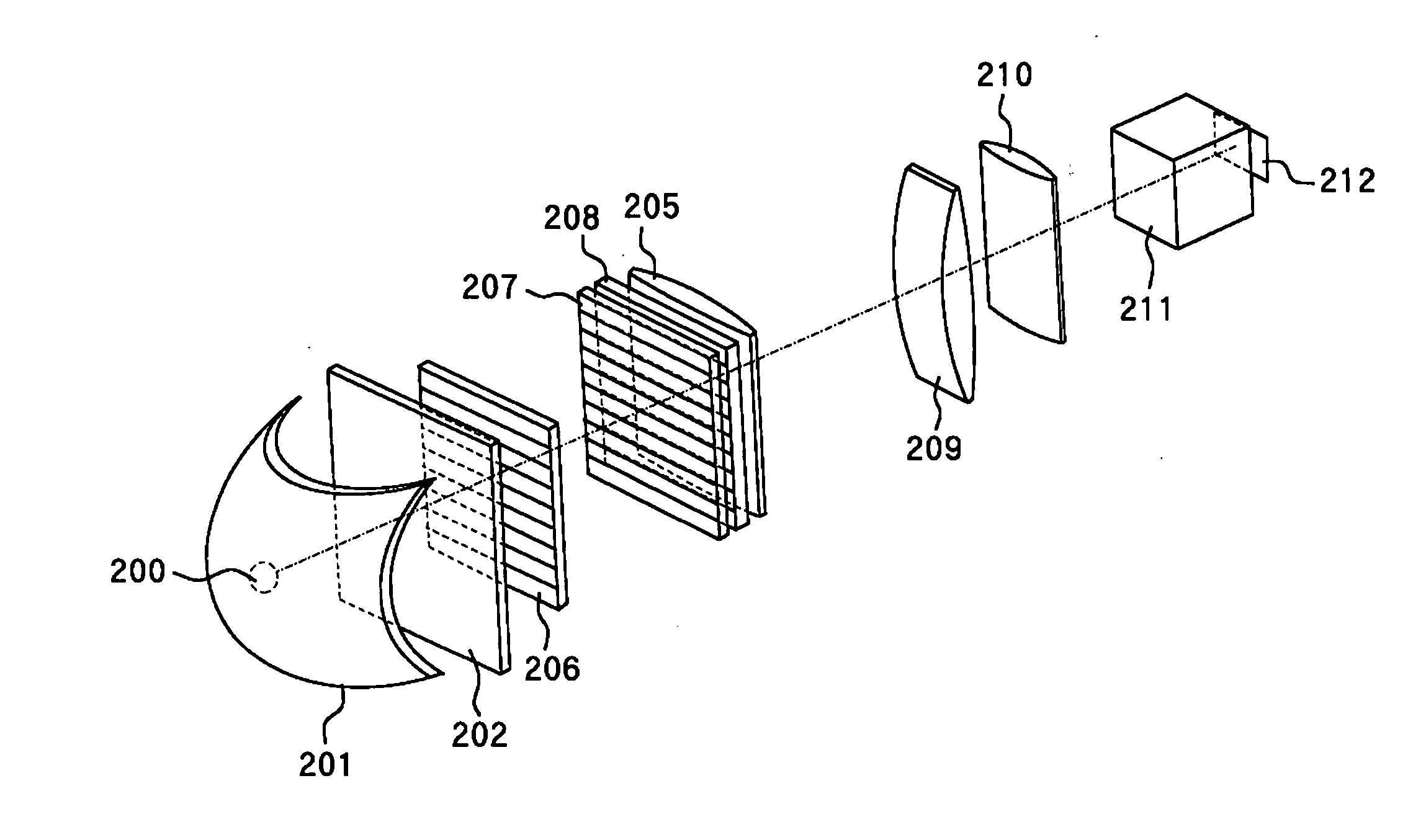
[0041]FIG. 1 shows the structure of an illumination optical system which is Embodiment 1 of the present invention. In FIG. 1, reference numeral 200 shows a gas exciting lamp of a DC drive type (a discharge gas exciting arc tube of a DC drive type) serving as a light source. As the lamp 200, a high-pressure mercury lamp, a metal halide lamp, a xenon lamp or the like is used. The light source lamp 200 is used in combination with a parabolic reflecting mirror 201 to produce a generally collimated visible light beam.

[0042] To provide a high-quality collimated luminous flux with the smallest possible divergence (the smallest possible divergence angle), the light source lamp 200 has a minimized discharge gap designed to limit an electron excited area in a gas. A DC bias is applied between a cathode and anode electrodes to produce a point source with high luminance on the side (in the vicinity) of the cathode electrode.

[0043] Of the luminous flux emitted from a lamp unit formed of the li...

embodiment 2

[0124]FIG. 11 shows the overall optical system in a projection display apparatus which is Embodiment 2 of the present invention.

[0125] In FIG. 11, reference numeral 1 schematically shows the illumination optical system described in Embodiment 1. A representation on the left in the frame in the figure shows the illumination optical system on the right viewed from an arrow D.

[0126] Reference numerals 2R, 2G, and 2B show reflection type liquid crystal modulation panels (hereinafter referred to as liquid crystal modulation panels) for read, green, and blue, respectively. Reference numeral 3 shows a light modulation panel driver which converts an external video input signal from an image information supply apparatus such as a personal computer, a television, a VCR, and a DVD player, not shown, into a driving signal for driving the liquid crystal modulation panels 2R, 2G, and 2B. Each of the liquid crystal modulation panels 2R, 2G, and 2B forms an original image with liquid crystal corr...


PUM


Abstract

An illumination optical system is disclosed, which provides a luminous flux with a small incident angle on an illumination surface in one axis direction on a section of the luminous flux. The illumination optical system can suppress a reduction in light amount by a mask provided for a polarization conversion element. The illumination optical system has a light source and an optical integrator. The optical integrator uses a lens array to perform splitting of a luminous flux from the light source. The illumination optical system has the polarization conversion element including a polarization beam splitter array, a plurality of ½ wave plates, and a mask. The light source is a discharge gas exciting arc tube of a DC drive type.

Description

CROSS-REFERNCE TO RELATED APPLICATIONS [0001] This application is a continuation of U.S. patent application Ser. No. 10 / 790,977 filed on Mar. 1, 2004.BACKGROUND OF THE INVENTION [0002] 1. Field of the Invention [0003] The present invention relates to an illumination optical system and a projection display optical system which are used in a projection display apparatus or the like. [0004] 2. Description of Related Art [0005] Conventionally, in a projector type display (a projection display apparatus), a liquid crystal display panel or a micromirror array device panel is typically used as a light modulation element for switching to control transmission and shielding or deflection of light to project a selected light pattern onto a screen, thereby displaying an image on the screen. [0006] In the projector which employs the liquid crystal display panel or the micromirror array device panel as the light modulation element, it is important to use light from a light source with high effici...

Claims


Application Information

Patent Timeline
Patent Type & Authority Applications(United States)
IPC IPC(8): G03B21/14G02B27/00G02B5/04G02B27/18G02B27/28G03B21/00
CPCG02B27/283G03B21/14G03B21/26G03B21/2073G03B21/208
Inventor KOIDE, JUN
Owner CANON KK
Why Eureka
Try Eureka