Photoelectrochemical determination of chemical oxygen demand

Inactive Publication Date: 2006-09-14
AQUA DIAGNOSTIC
View PDF1 Cites 92 Cited by
  • Summary
  • Abstract
  • Description
  • Claims
  • Application Information

AI Technical Summary

Benefits of technology

[0046] A supporting electrolyte is used to determine the background photocurrent and to dilute the water sample to be tested. The determination of the background photocurrent measures the oxidation of water and this can be deducted from the sample reading to give the photocurrent due to the oxidation of organic material in the sample. This measurement may be made as a separate measurement to the sample reading or when conducting an exhaustive degradation the final steady curren

Problems solved by technology

Nearly all domestic and industrial wastewater effluents contain organic compounds, which can cause detrimental oxygen depletion (or demand) in waterways into which the effluents are released.
Despite their widespread use for estimating oxygen demand, both BOD and COD methodologies have serious technological limitations.
Both methods are time consuming and very expensive, costing water industries and local authorities in excess of $1 billion annually worldwide.
Other problems with the BOD assay include: limited linear working range; complicated, time consuming procedures; and questionable accuracy and reproducibility (the standard method accepts a relative standard deviation of ±15% for replicate BOD5 analyses).
More importantly, interpretation of BOD results is difficult since the results tend to be specific to the body of water in question, depend on the pollutants in the sample solution and the nature of the microbial seed used.
In addition, the BOD methodologies cannot be used to assess the oxygen demand for many heavily polluted water bodies because of inhibitory and toxic effects of pollutants on the heterotropic bacteria.
Despite this, the method has several drawbacks in that it is time consuming, requiring 2-4 hours to reflux samples, and utilises expensive (e.g. Ag2SO4), corrosive (e.g. concentrated H2SO4) and highly toxic (Hg(III) and Cr(VI)) reagent

Method used


Image

  • Photoelectrochemical determination of chemical oxygen demand
  • Photoelectrochemical determination of chemical oxygen demand
  • Photoelectrochemical determination of chemical oxygen demand

Examples


Example

EXAMPLE 1

Quantification of COD Using Photocurrent

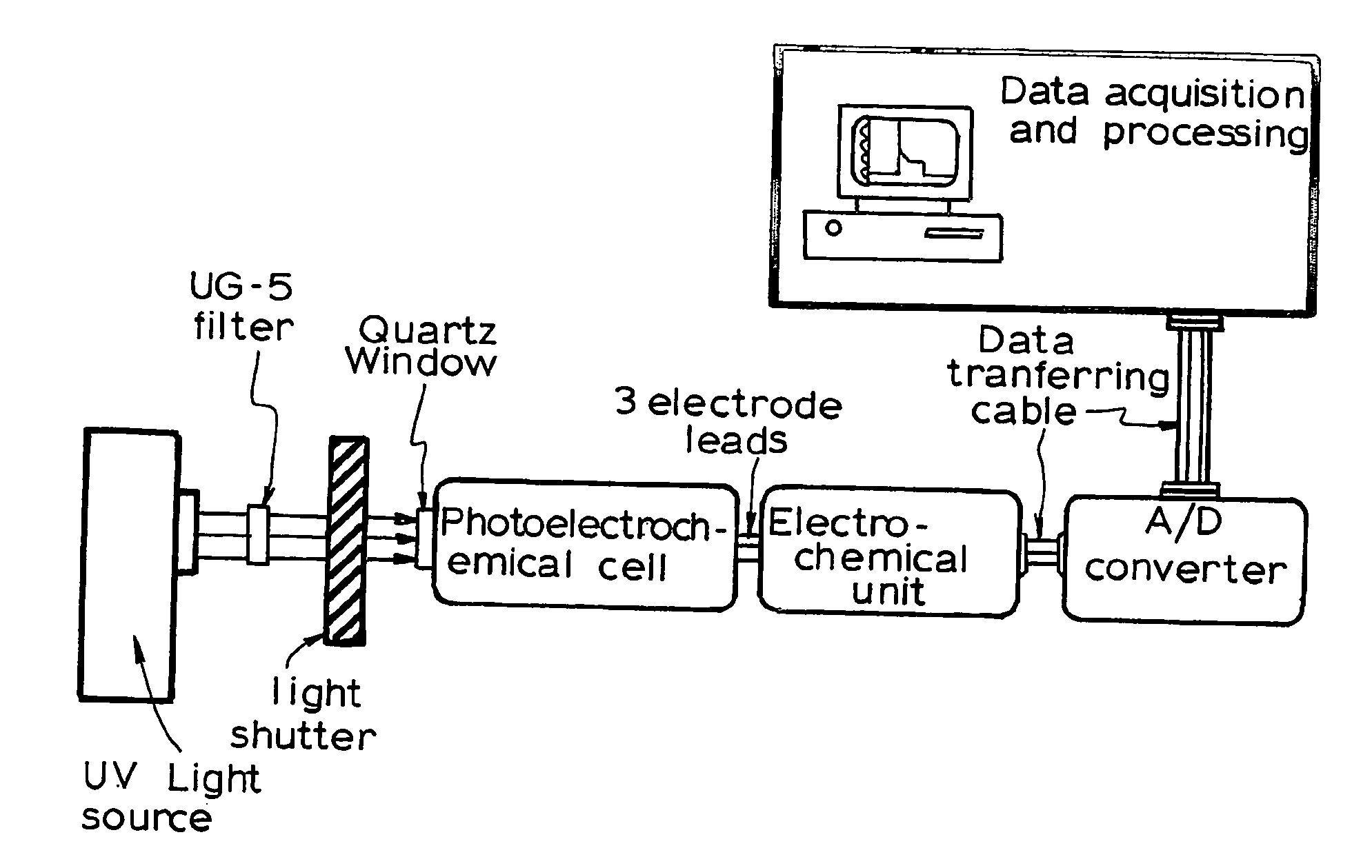
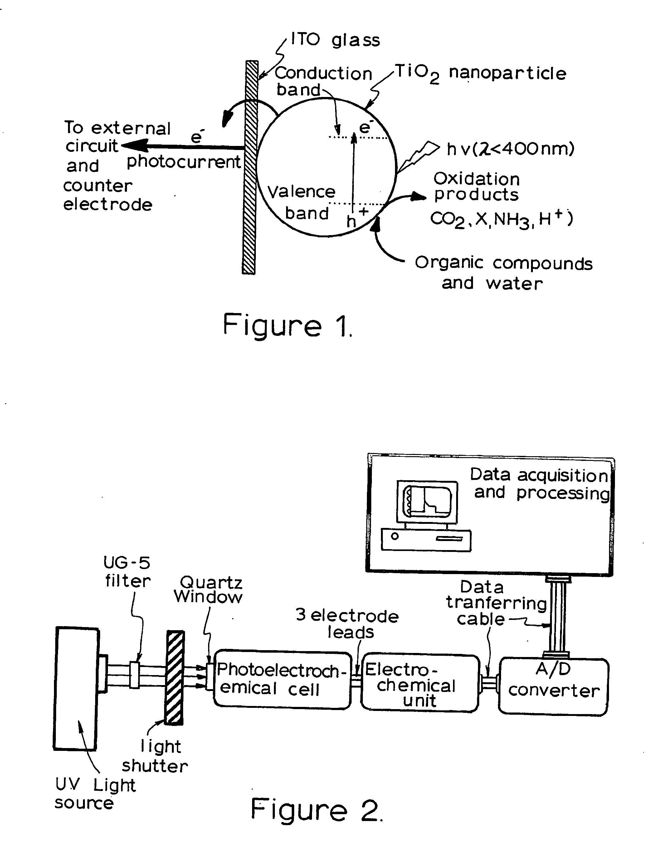
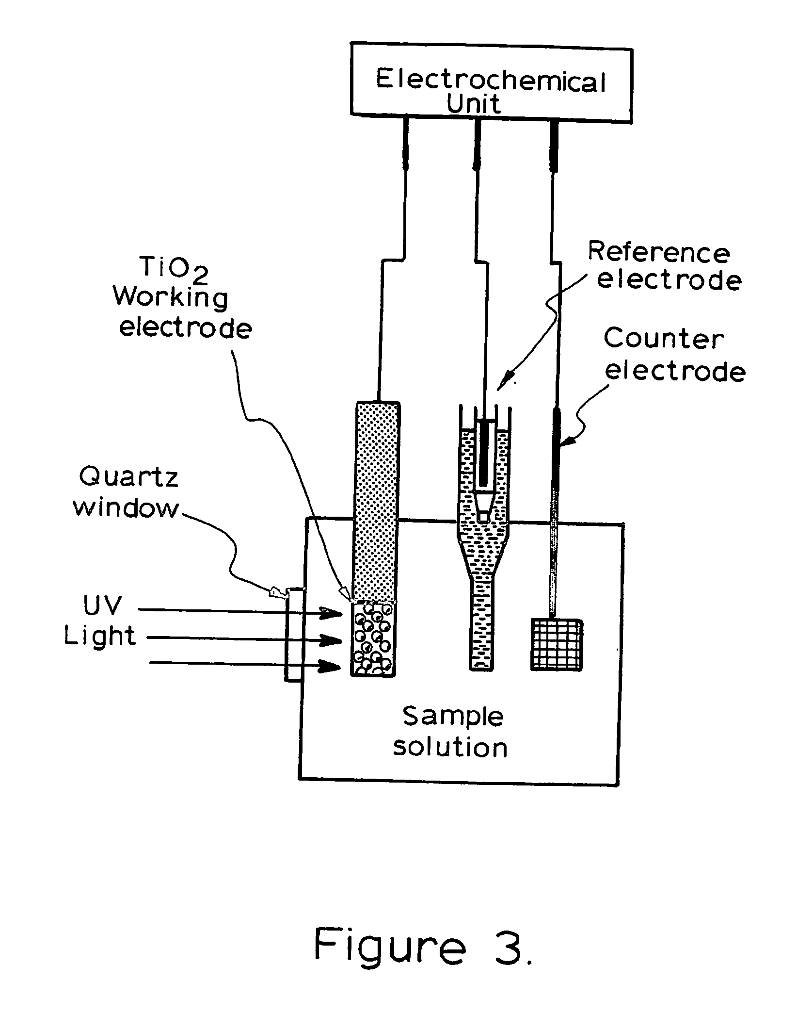
[0129] The photoelectrochemical experiment was performed in a three-electrode electrochemical batch cell with a quartz window for illumination as shown in FIG. 3 The TiO2 film electrode was placed in an electrode holder with ca. 0.65 cm2 left unsealed to be exposed to the solution for illumination and photoelectrochemical reaction. 0.1M NaNO3 solution was used as the supporting electrolyte. A potential bias of +0.2V was applied at the electrode and limiting photocurrents were obtained for different organic compound concentrations when the current reached steady state. The limiting photocurrent differences between samples and the blank 0.1M NaNO3 solution were taken as analytical signals, which are directly linear to organic compound concentrations within diffusion control. A linear relationship between the analytical signal and COD value was then acquired after the concentration was converted into COD value.

Example

EXAMPLE 2

Quantification of COD Using Charges

[0130] In this case the experiment was carried out in a thin-layer photoelectrochemical cell as shown in FIGS. 4 and 5. A potential bias of +0.20V was applied and 2M NaNO3 was used as supporting electrolyte. Firstly, a 2M NaNO3 electrolyte solution was injected into the thin-layer photoelectrochemical cell with a syringe and a blank transient photoelectrolysis was run as a blank sample. The photocurrent-time profile was recorded until the photocurrent reached steady state. Then samples containing organic compounds and 2M NaNO3 were injected into the thin-layer cell and the sample transient photoelectrolysis was run. The photocurrent-time profile was recorded until the photocurrent attained steady state, indicating the organic compounds have been exhaustively photoelectrolysed. The cell was washed with supporting electrolyte solution between each sample injection. Integrating the photocurrent-time profile gives the photocatalytic oxidatio...

Example

EXAMPLE 3

Quantification of COD Using Charges and FIA

[0131] Besides the use of the thin-layer photoelectrochemical cell, a flow injection analysis (FIA) system was incorporated into the COD determination. With the combination of FIA, automatic COD determination was realised. In this case, the injection of samples and cell cleaning was controlled by a FIA controlling system as shown in FIG. 6 (a). Pump 1 achieves the blank sample (R1) injection and cell cleaning while Pump 2 does the sample injection (R2). A potential bias of +0.20V was applied and 2M NaNO3 was used as supporting electrolyte (blank sample). Firstly, a 2M NaNO3 electrolyte solution was pumped into the thin-layer photoelectrochemical cell by Pump 1 and a blank transient photoelectrolysis was run as a blank sample. The photocurrent-time profile was recorded until the photocurrent reached steady state. Then samples containing organic compounds and 2M NaNO3 were pumped into the thin-layer cell by Pump 2 and the sample tr...


PUM


Abstract

A method for determining chemical oxygen demand of a water sample comprises the steps of (a) applying a constant potential bias to a photoelectrochemical cell, having a photoactive working electrode (e.g. a layer of titanium dioxide nanoparticles coated on an inert conductive substrate) and a counter electrode, and containing a supporting electrolyte solution; (b) illuminating the working electrode with a light source and recording the background photocurrent produced at the working electrode from the supporting electrolyte solution; (c) adding a water sample, to be analyzed, to the photoelectrochemical cell; (d) illuminating the working electrode with a light source and recording the total photoelectrocurrent produced with the sample; (e) determining the chemical oxygen demand according to the type (exhaustive or non-exhaustive) of degradation conditions employed.

Description

FIELD OF THE INVENTION [0001] This invention relates to a new method for determining oxygen demand of water using photoelectrochemical cells. In particular, the invention relates to a new photoelectrochemical method of determining chemical oxygen demand of water samples using a titanium dioxide nanoparticulate semiconductive electrode. BACKGROUND TO THE INVENTION [0002] Nearly all domestic and industrial wastewater effluents contain organic compounds, which can cause detrimental oxygen depletion (or demand) in waterways into which the effluents are released. This demand is due largely to the oxidative biodegradation of organic compounds by naturally occurring microorganisms, which utilize the organic material as a food source. In this process, carbon is oxidised to carbon dioxide, while oxygen is consumed and reduced to water. [0003] Standard analytical methodologies for the determination of aggregate properties such as oxygen demand in water are biochemical oxygen demand (BOD) and ...

Claims


Application Information

Patent Timeline
IPC IPC(8): G01N33/18G01N27/30
CPCG01N27/305G01N33/1806H01G9/2031Y10T436/204998C25B1/003Y10S436/905Y10T436/235Y02E10/542Y02P20/133C25B1/55G01N33/18G01N27/413G01N27/30G01N31/10
Inventor ZHAO, HUIJUN
Owner AQUA DIAGNOSTIC
Why Eureka
Try Eureka