Mass spectrometer and mass analysis method
a mass spectrometer and mass analysis technology, applied in the field of mass spectrometers, can solve the problems of reducing the usability of ions, affecting the separation effect of ions, so as to achieve effective separation of ions. the effect of high sensitivity
- Summary
- Abstract
- Description
- Claims
- Application Information
AI Technical Summary
Benefits of technology
Problems solved by technology
Method used
Image
Examples
first embodiment
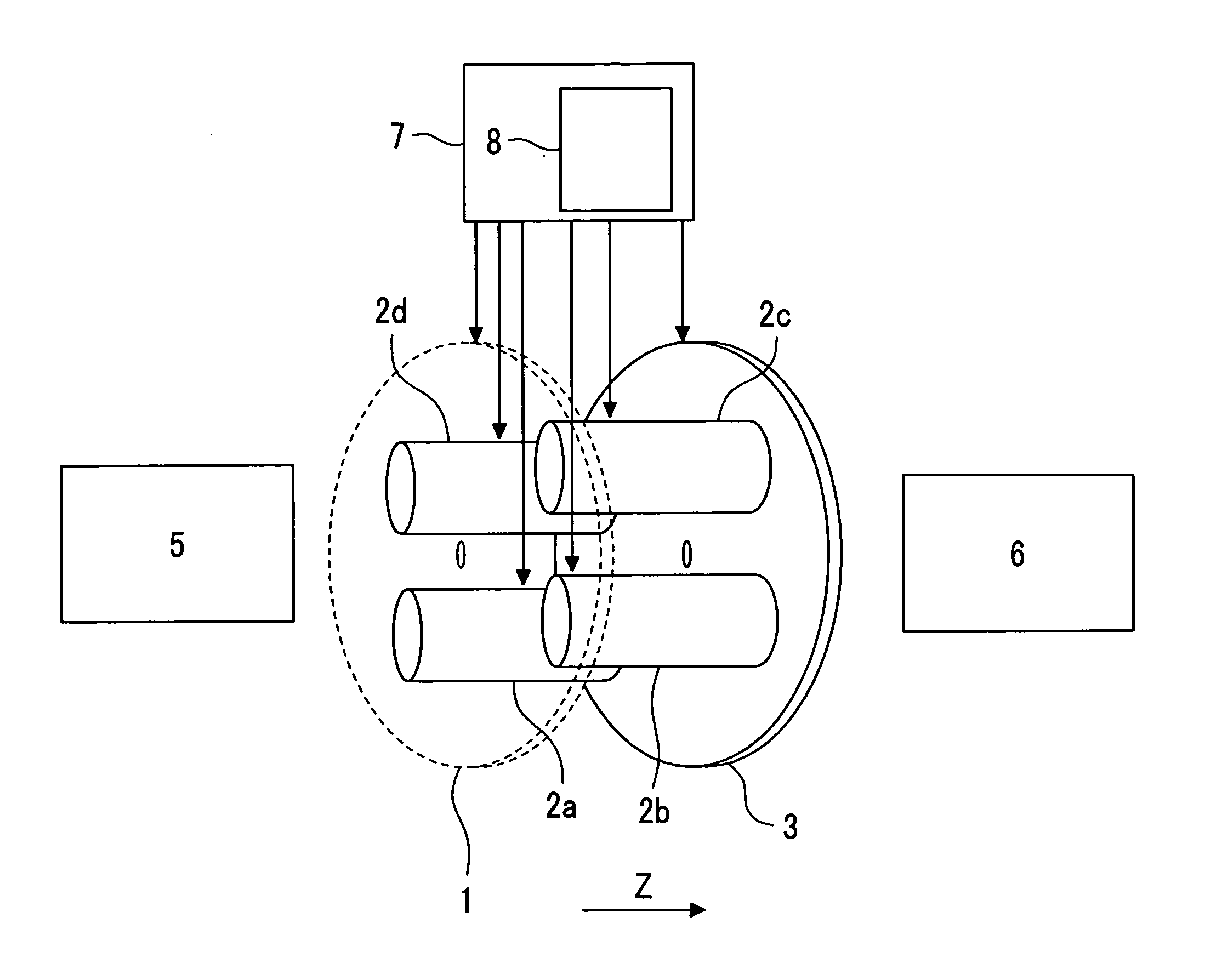
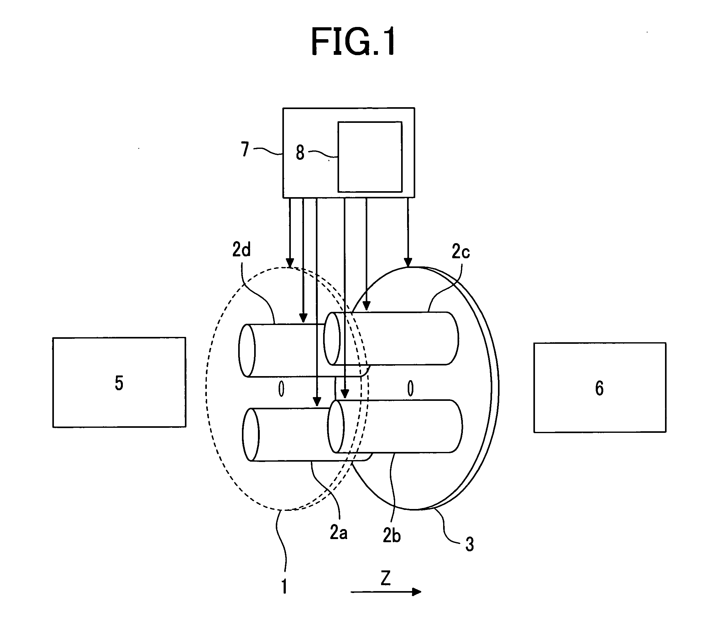
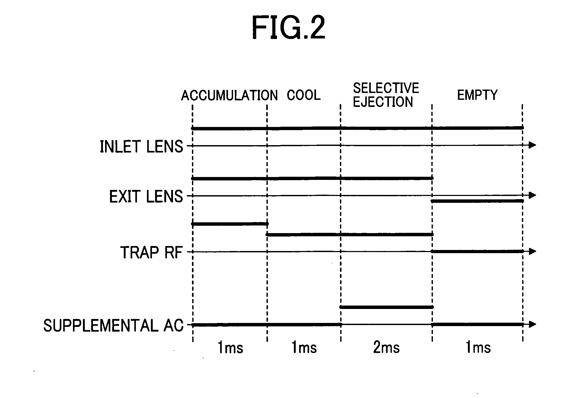
[0029]FIG. 1 is a diagram of a configuration of a mass spectrometer using a linear trap section enabling charge separation according to a first preferred embodiment of the invention. Ions are generated by an ion source 5, such as an electrospray ion source, or a Matrix Assisted Lasor Desorption Ionization ion source. The ions generated are introduced via a differential pumping region, and an ion guide, which are not shown, into a linear trap comprising four rods 2, and end lenses 1 and 3 on both sides thereof. Application of a voltage to the linear trap is performed by a power supply 7 for a controller. Typically, the length of the rod 2 is set to 7.0 mm, the diameter of a pole to 7.0 mm, a distance between the poles to 7.0 mm, and a distance between the rod 2 and the end lenses 1, 3 to about 10 mm. Trap RF voltages (frequency: 500 to 3 MHz (typically, 1 MHz), and amplitude: 100 V to 5 kV) are applied to the rods 2 such that the adjacent rods are subjected to the voltages in opposit...
second embodiment
[0039] In the above-mentioned embodiment, charge separation of ions with the specific range of mass-to-charge ratios is performed using the supplemental AC voltage with a single frequency. In a second preferred embodiment, charge separation of ions with a wide range of mass-to-charge ratios is also allowed. A composite wave with a frequency fN represented by the following formula (8) (typically 1 to 50 kHz, changed by 0.5 kHz) is used as a supplemental AC voltage. ∑NANsin(2π fNt+ϕN)
In this case, since an appropriate voltage is different depending on the mass-to-charge ratio (frequency), it is necessary to give a voltage gain AN which differs depending on each frequency component fN. Ions resonate with only the frequency component in the vicinity of the resonance frequency to be ejected into the mass spectrometry section 6. Also in this case, a frequency and a voltage gain AN of a supplemental AC voltage for ejecting only ions with high charge and retaining ions with low cha...
third embodiment
[0040] In the third embodiment, the charge separation trap described in the first embodiment is applied particularly to an ion source and an intermediate section (differential pumping region) of a mass spectrometry section. This application is illustrated in FIG. 6. Ions are generated by an atmospheric pressure ion source 101, such as an electrospray ion source, an atmospheric pressure chemical ion source, an atmospheric pressure light ion source, or an atmospheric pressure matrix assisted laser desorption ion source. The ions generated are introduced into a first differential pumping region 103 via a first porous lens 102. The first differential pumping region is exhausted by a vacuum pump (not shown), and is maintained at 1 to 10 Torr (130 to 1300 Pa, the main component being air) The ions pass through a second porous lens 104 to be introduced into a second differential pumping region 105 where the trap of the invention is disposed. In the second differential pumping region 105, a...
PUM
| Property | Measurement | Unit |
|---|---|---|
| Pressure | aaaaa | aaaaa |
| Pressure | aaaaa | aaaaa |
| Pressure | aaaaa | aaaaa |
Abstract
Description
Claims
Application Information
 - R&D
- Intellectual Property
- Life Sciences
- Materials
- Tech Scout
- Unparalleled Data Quality
- Higher Quality Content
- 60% Fewer Hallucinations
Browse by: Latest US Patents, China's latest patents, Technical Efficacy Thesaurus, Application Domain, Technology Topic, Popular Technical Reports.
© 2025 PatSnap. All rights reserved.Legal|Privacy policy|Modern Slavery Act Transparency Statement|Sitemap|About US| Contact US: help@patsnap.com


