Phosphor and manufacturing method of the same, and light emitting device using the phosphor

a technology of phosphor and manufacturing method, which is applied in the direction of discharge tube/lamp details, discharge tube luminescent composition, discharge tube luminescent screen, etc., can solve the problems of short life span, loss of balance of blue color and yellow color emission intensity, and deterioration of color rendering properties which are essential factors of illumination, etc., to achieve excellent emission efficiency, emission intensity and luminance, and easy pulverization

Inactive Publication Date: 2006-10-05
MITSUBISHI CHEM CORP
View PDF54 Cites 70 Cited by
  • Summary
  • Abstract
  • Description
  • Claims
  • Application Information

AI Technical Summary

Benefits of technology

[0029] According to the phosphor of any one of the first to eighth aspects, the phosphor having the excellent emission efficiency, emission intensity and luminance is provided, having the emission spectrum with a high efficient excitation band in the wavelength range of the near ultraviolet / ultraviolet, and a broad peak in the range of blue color (in the peak wavelength range from 400 nm to 500 nm) when the phosphor is irradiated with the light in the wavelength range of the near ultraviolet / ultraviolet.
[0030] According to the phosphor of either of the ninth or tenth aspect, the phosphor thus obtained is in a powdery state, therefore is easy to be pulverized, and can be applied on various places as a paste. In addition, the average particle size (D50) of the phosphor is not less than 1.0 μm and not more than 20.0 μm, and therefore coating density can be increased, whereby a coating film having high emission intensity and luminance can be obtained.
[0031] According to the manufacturing method of the phosphor of any one of the eleventh to thirteenth aspects, the phosphor according to any one of the first to tenth aspects can be manufactured at a low manufacturing cost.
[0032] According to the manufacturing method of the phosphor of the fourteenth aspect, the carbonate serving as the raw material acts as flux, thereby accelerating a solid phase reaction, and the phosphor having excellent emission characteristics and powder characteristics can be manufactured.
[0033] According to the light emitting device of any one of the fifteenth to seventeenth aspects, a high efficient light emitting device can be obtained, having a desired emission color and high emission intensity and luminance.

Problems solved by technology

At present, a discharge type fluorescent lamp and an incandescent bulb used as the illumination device involve problems that a harmful substance such as mercury is contained, and life span is short.
However, the problem of the white LED illumination is that the emission on the long-wavelength side of visible light range, specifically the emission of red color component is insufficient although the white LED illumination has a high luminance, thereby deteriorating in the color rendering properties which are essential factors of illumination.
However, problems are involved in the white LED illumination, in which the high luminance blue LED and the garnet yellow phosphor are combined, such that the garnet yellow phosphor does not have a flat broad excitation band near the excitation wavelength of 460 nm, there are variances in the emission intensity and the peak wavelength of the high luminance blue LED, and a balance of the emission intensity of blue color and yellow color is lost, thereby changing a color tone of the white light, because the emission intensity of transmitted blue light depending on a film thickness is changed when the phosphor is applied on the LED.
However, there is no high efficient and high luminance R,G,B and other phosphor such as the YAG:Ce phosphor used in combination with the high luminance blue LED and the garnet yellow phosphor, and therefore a satisfactory white LED illumination can not be obtained.
However, although the nitrogen-containing phosphor of the aforementioned patent document 1 has the emission spectrum with a broad peak, the emission intensity under the excitation of the excitation light of near ultraviolet / ultraviolet does not meet a satisfactory level, and therefore a sufficient emission intensity and luminance can not be obtained.
Thus, the phosphor of the patent document 1 is considered to be inadequate to be used in the light emitting device.

Method used


Image

  • Phosphor and manufacturing method of the same, and light emitting device using the phosphor
  • Phosphor and manufacturing method of the same, and light emitting device using the phosphor
  • Phosphor and manufacturing method of the same, and light emitting device using the phosphor

Examples


example 1

[0102] In an example 1, sample 1 to sample 6 were manufactured by procedures as will be described below. In the samples 1 to 6, SrSi7N10:Eu and SrSi7N10:Eu with some replacement of oxygen in nitrogen-site were prepared by firing at 1800° C.

[0103] First, the manufacturing method of SrSi7N10:Eu of the sample 1 will be explained. The commercially available Sr3N2(2N), Si3N4(3N), and Eu2O3(3N) were prepared as the raw materials, and each raw material was weighed to obtain 0.970 / 3 mol of Sr3N2, 7 / 3 mol of Si3N4, and 0.030 / 2 mol of Eu2O3, so that the molar ratio of each element becomes Sr:Si:Eu=0.970:7:0.030, and mixed by using the mortar in the atmospheric air. The raw materials thus mixed were put in the BN crucible, and after vacuously exhausting the inside of the furnace once, temperature was increased at 15° C. / min up to 1800° C. with the pressure in the furnace set at 0.05 MPa in the nitrogen atmosphere (flow state at 20.0 L / min), and the raw materials were retained / fired at 1800° C...

example 2

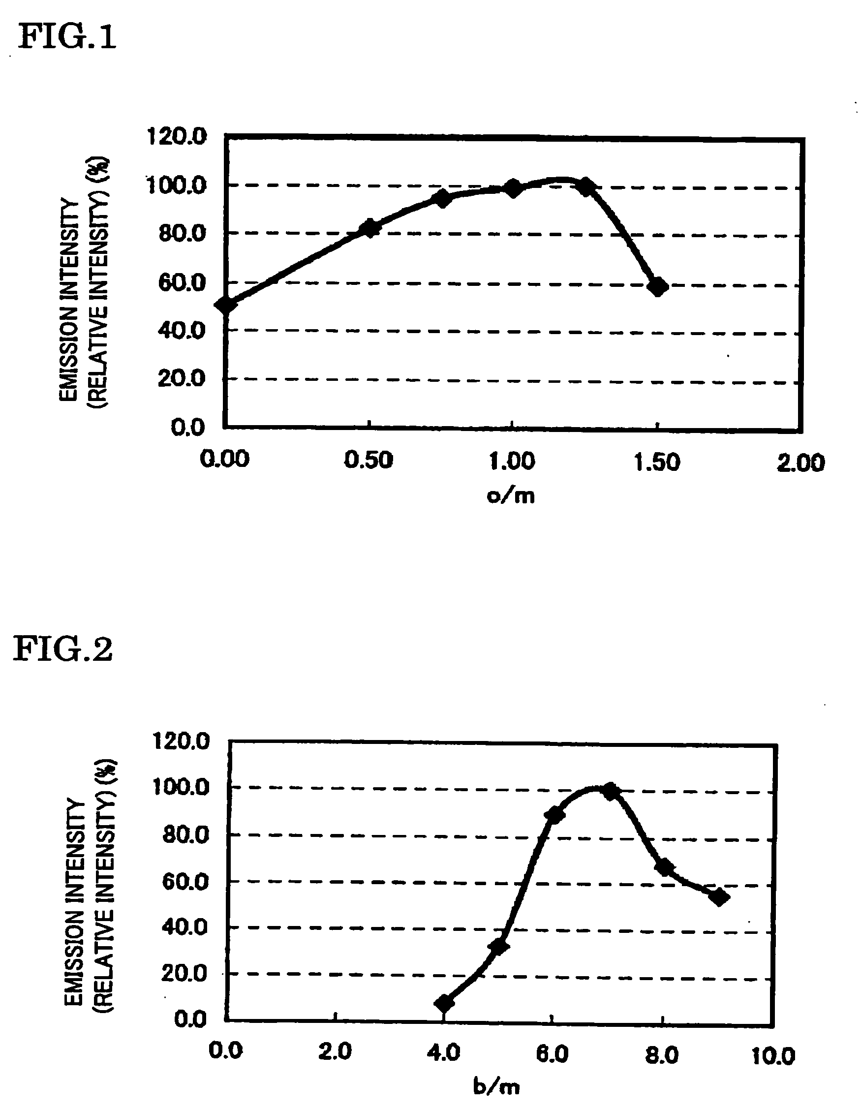
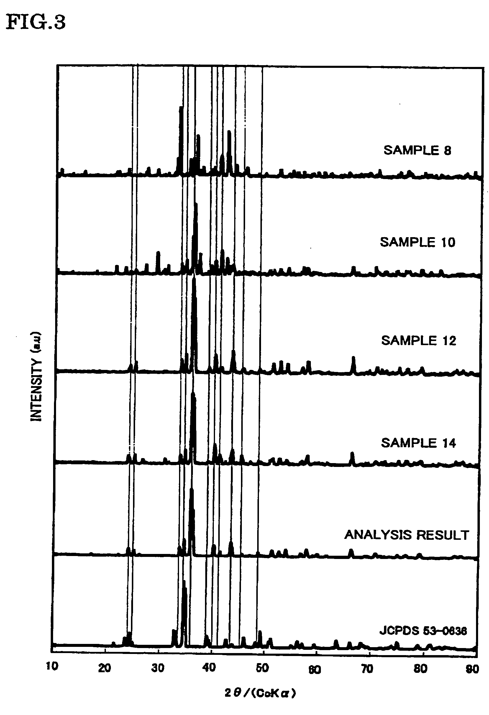
[0111] In the example 2, samples 7 to 14 were manufactured by the following procedure.

[0112] The samples 7 to 14 were manufactured in such a manner that the molar ratio of Sr, Al, and O was fixed to 1, 1, 1, respectively and the b / m ratio thereof was changed, and the raw materials were then fired at 1800° C., in the phosphor expressed by the composition formula SrAlSibONn:Eu (Eu / (Sr+Eu)=0.030, n=2 / 3m+a+4 / 3b−2 / 3o, m=1, a=1, and o=1) in which Al was further added to the constituent elements Sr, Si, O and N of the matrix body of the example 1, as the constituent element of the matrix body.

[0113] In addition, in the manufacture of each sample, the phosphor sample was manufactured in the same way as the sample 1 of the example 1, excepting that the commercially available SrCO3(3N), AlN(3N), Si3N4(3N), and Eu2O3(3N) were prepared as the raw materials, and the mixing ratio of each raw material was adjusted to become a predetermined b / m ratio. Specifically, the b / m ratio is adjusted to be...

example 3

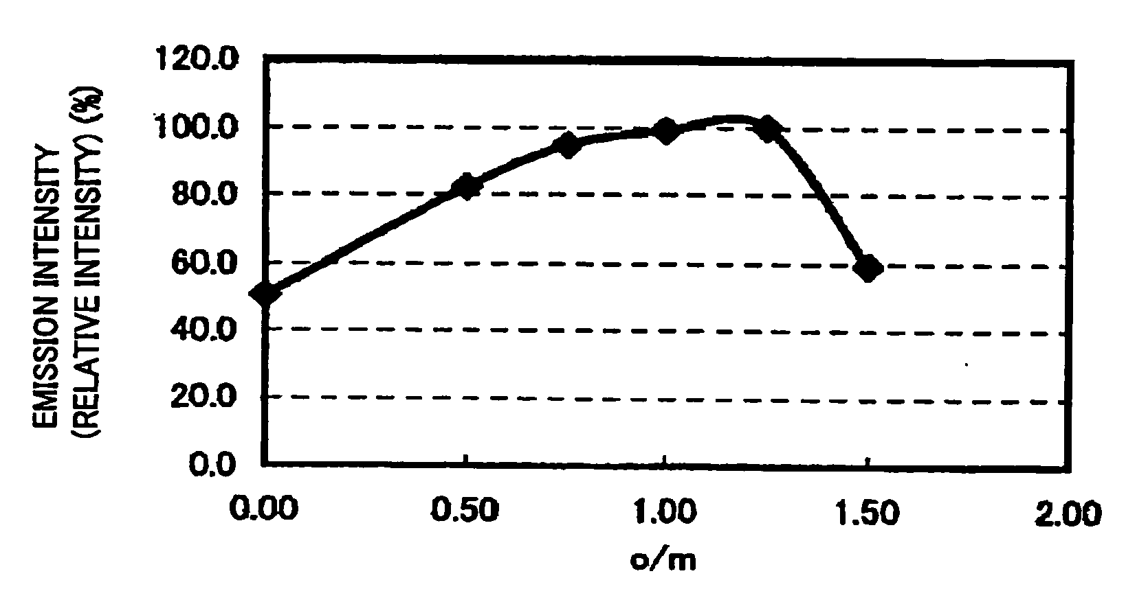
[0133] Samples 15 to 23 were manufactured in such a manner that the molar ratio of Sr, Al, and Si was fixed to 1, 1, 7, respectively and an o / m ratio was changed, and the raw materials were then fired at 1800° C., and the emission intensity was measured, in the phosphor expressed by the composition formula SrAlSi7.0OoNn:Eu(Eu / (Sr+Eu)=0.030, n=2 / 3m+a+4 / 3b−2 / 3o, m=1, a=1, and b=7). In the manufacture of each sample, the commercially available Sr3N2(2N), SrCO3(3N), Al2O3(3N), AlN(3N), Si3N4(3N), and Eu2O3(3N) were prepared as the raw materials, and in the same way as the sample 1 of the example 1, the phosphor sample was manufactured excepting that the mixing ratio of each raw material was adjusted to a predetermined o / m ratio. However, the o / m ratio thus adjusted was set at o / m=0 (sample 15), o / m=0.50 (sample 16), o / m=0.75 (sample 17), o / m=1.00 (sample 18), o / m=1.25 (sample 19), o / m=1.50 (sample 20), o / m=1.75 (sample 21), o / m=2.00 (sample 22), and o / m=2.50 (sample 23).

[0134] The peak...


PUM


Abstract

To provide a phosphor having an emission spectrum with a broad peak in a range of blue color (peak wavelength range from 400 nm to 500 nm) and a broad and flat excitation band in a range of near ultraviolet / ultraviolet, and having an excellent emission efficiency and emission intensity / luminance, a manufacturing method of the same, and a light emitting device using the phosphor. The phosphor is provided, which is given as a general composition formula expressed by MmAaBbOoNn:Z, (where element M is the element having bivalent valency, element A is the element having tervalent valency, element B is the element having tetravalent valency, O is oxygen, N is nitrogen, and element Z is more than one kind of element acting as an activator.), satisfying 5.0<(a+b) / m<9.0, 0≦a / m≦2.0, 0≦o<n, and n=2 / 3m+a+4 / 3b−2 / 3o, and having an emission spectrum with a maximum peak wavelength from 400 nm to 500 nm under an excitation of the light in a wavelength range from 350 nm to 430 nm.

Description

TECHNICAL FIELD OF THE INVENTION [0001] The present invention relates to a phosphor containing nitrogen used for a cathode-ray tube (CRT), a display such as a field emission display (FED) and a plasma display (PDP), and an illumination device such as a fluorescent lamp and a fluorescent display tube, and an illumination device such as a back light for liquid-crystal display and a method of manufacturing therefore, and also to a light emitting device such as a white LED illumination in which a semiconductor light emitting element (LED) and the phosphor are combined. BACKGROUND OF THE INVENTION [0002] At present, a discharge type fluorescent lamp and an incandescent bulb used as the illumination device involve problems that a harmful substance such as mercury is contained, and life span is short. However, in recent years, a high luminescence LED emitting light of near ultraviolet / ultraviolet to blue color has been developed in sequence, and the white LED illumination for the practical...

Claims


Application Information

Patent Timeline
Patent Type & Authority Applications(United States)
IPC IPC(8): H01J1/62H01J63/04
CPCC09K11/7734C09K11/0883C09K11/77347C09K11/77348
Inventor SAKANE, KENJINAGATOMI, AKIRA
Owner MITSUBISHI CHEM CORP
Why Eureka
Try Eureka