High speed imaging system

a high-speed imaging and imaging system technology, applied in the field of high-speed imaging systems, can solve the problems of periodic vibration and/or incomplete contact of the vocal folds, significant social and occupational handicaps of individuals, and symptomatic of serious, even life-threatening underlying disease, etc., to improve the current clinical laryngeal imaging instrumentation and speed up signal processing.

Inactive Publication Date: 2006-10-19
INCRYS
View PDF3 Cites 31 Cited by
  • Summary
  • Abstract
  • Description
  • Claims
  • Application Information

AI Technical Summary

Benefits of technology

[0016] Generally speaking, in accordance with the invention, a high speed scanning system is provided which can image and provide diagnosis for objects moving in constrained locations. The system can be used to image engine parts, vocal cords, heart valves and the like. Systems in accordance with embodiments of the invention can i...

Problems solved by technology

Voice problems can cause significant social and occupational handicaps for individuals.
They can be a symptom of serious, even life-threatening underlying disease.
Voice problems can result from factors that cause a periodic vibration and/or incomplete contact of the vocal folds during each cycle of vibration.
Imaging challenges for achieving noninvasive, affordable instrumentation include the relatively awkward access to the vocal folds, their high rate of vibration and the need to record up to approximately 10 seconds of continuous imaging.
Significant limitations of stroboscopy are its dependence on periodic vocal fold vibration and poor correlation with the acoustic signal.
Further, it is generally not possible to derive accurate estimates of anatomical dimensions due to the dependence of the size of the image on an unknown distance of the endoscope tip from the vocal folds.
These weaknesses can limit the accuracy of diagnosis of disease, and impede advancement of our understanding of vocal physiology, which underlies the prevention, and treatment of voice disorders.
These can be unsatisfactory alternatives to videostroboscopy and the acceptable clinical application of these technologies has not been fully achi...

Method used


Image

  • High speed imaging system
  • High speed imaging system
  • High speed imaging system

Examples


Embodiment Construction

[0029] Systems in accordance with the invention can produce high quality still and moving images of moving structures in tight, hard to access locations. Though the primary application for systems in accordance with the invention is likely to involve generating images and methods of diagnosis relating to the vocal cords, the invention can find applications in other areas, such as imaging heart valves, engine systems and other applications.

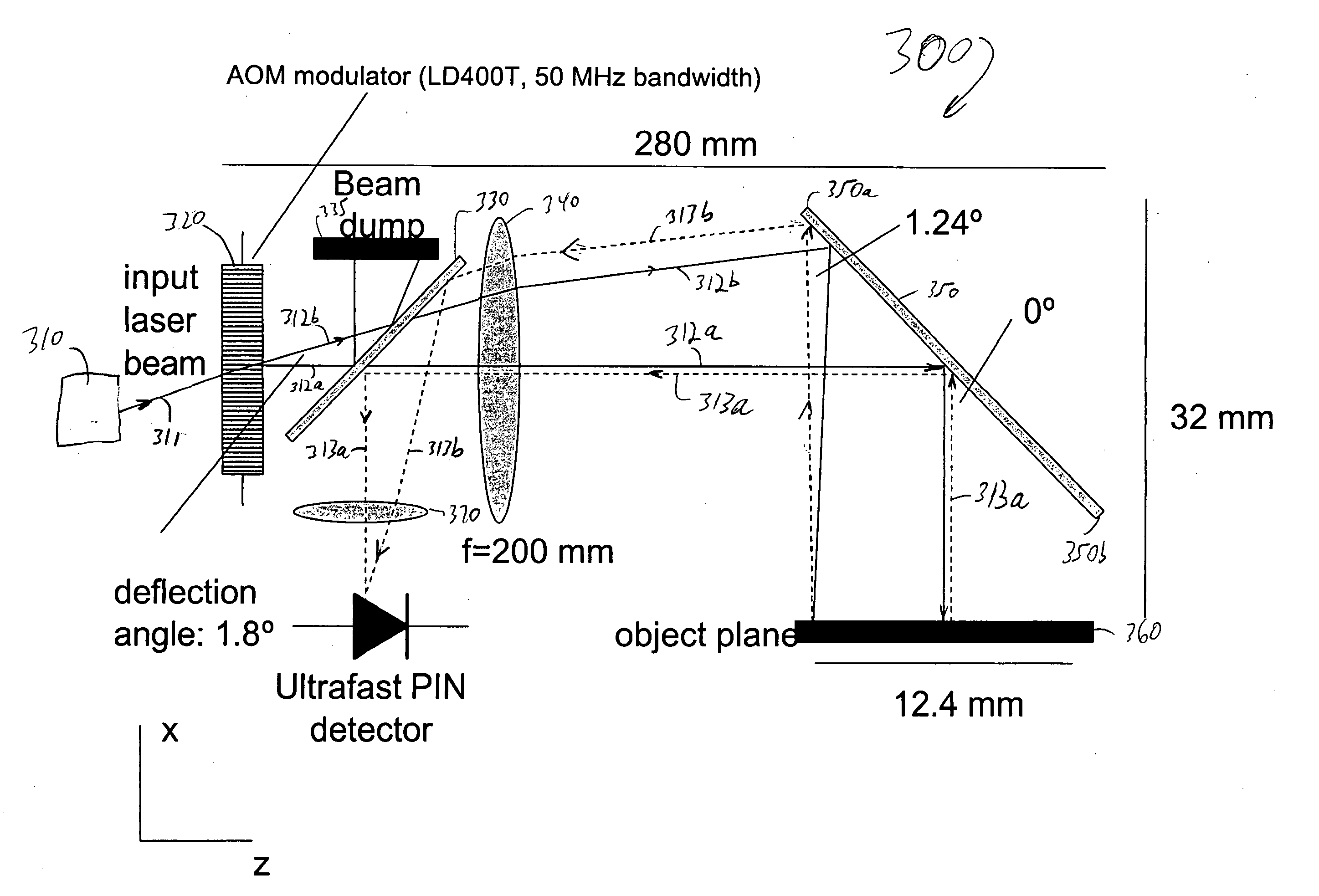
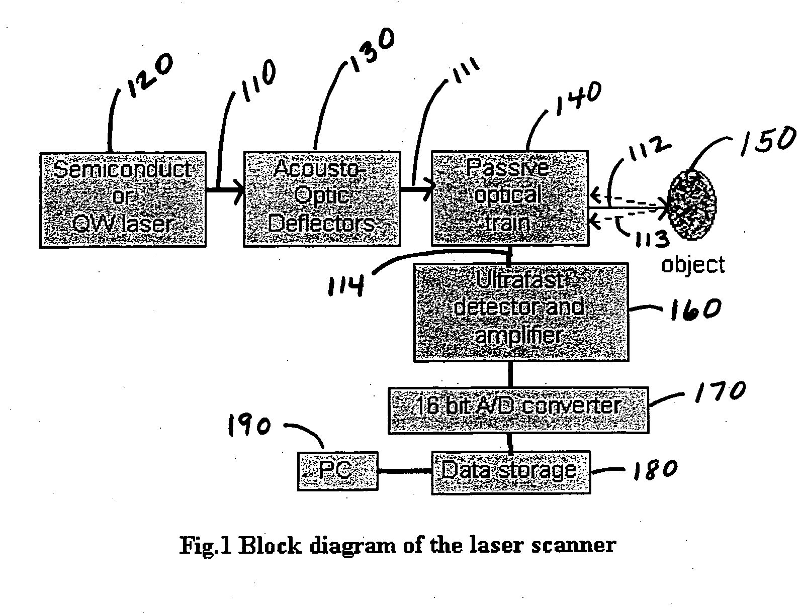
[0030] The core optical sub-system that enables generation of vocal fold imaging in accordance with an embodiment of the invention is a laser scanner. The laser scanner performance and capability relies in turn on several optoelectronic components. A functional block diagram of a vocal fold imaging laser scanner 100 assembled in accordance with an embodiment of the invention is shown in FIG. 1 to form image, a beam of coherent light 110 of a fixed wavelength (preferably selected from λ=700-1000 nm, preferably the 800-980 nm range) is output from a...


PUM


Abstract

A system for imaging high speed moving objects, for example, using a scanning beam and beam delivery optics with fast signal processing. It can allow for vocal fold imaging at up to or exceeding approximately 1000 frames per second with grayscale resolution as high as about 100 micrometers or higher and up to about a 12.4 mm square or larger viewing area. The invention can provide imaging of vocal fold vibration that correlates completely with a synchronously-acquired acoustic voice signal. This can enable physicians, voice therapists and research scientists to understand the consequences of abnormal laryngeal dynamics, rather than being limited to simply observing the dynamics. Further, the application of laser technology will allow for accurate measurements of dimension. This can objectify examination findings and treatment outcomes measurement, helping to overcome the serious limitations of current perceptual-based judgments.

Description

BACKGROUND OF INVENTION [0001] The invention relates generally to a high speed imaging system and more particularly to an imaging system that can image objects moving at high speed in cramped quarters. Such a system can be useful for imaging the vocal cords and diagnosing abnormalities. The system can also be used to determine the precise position of the object whether it is stationary or moving. [0002] Voice problems can cause significant social and occupational handicaps for individuals. They can be a symptom of serious, even life-threatening underlying disease. Visualization of vocal fold vibration can be essential for the treatment of individuals with many voice disorders. [0003] Estimates of the prevalence of voice disorders range from 3% to 7% of the general population. See Colton R H, Casper J K, Understanding Voice Problems, 2nd Ed. Baltimore, Md., Williams and Wilkins; 1996; Healy, W C, Ackerman, B L, Chappell, C R, Perrin K L, Stormer, J, The Prevalence of Communicative Di...

Claims


Application Information

Patent Timeline
IPC IPC(8): G10L21/00
CPCA61B1/2673
Inventor RUDERMAN, WARRENGANIKHANOV, FERUZ
Owner INCRYS
Why Eureka
Try Eureka