
Image bearing member, and image forming apparatus and process cartridge using the same

a technology of image bearing member and process cartridge, which is applied in the direction of electrographic process, instrumentation, corona discharge, etc., can solve the problems of increasing the dark decay of an image bearing member, significant productivity decline, background fouling, etc., and achieves the effect of stably performing image formation

Active Publication Date: 2006-10-26
RICOH KK
View PDF21 Cites 40 Cited by
  • Summary
  • Abstract
  • Description
  • Claims
  • Application Information

AI Technical Summary

Benefits of technology

[0016] Because of these reasons, the present inventors recognize that a need exists for an image bearing member, and corresponding image forming apparatus and process cartridge, which can form images without reducing the image density, causing background fouling, etc., even for an extended repetitive use and stably perform image formation from the first rotation of the image bearing member.
[0017] Accordingly, an object of the present invention is to provide an image bearing member, and corresponding image forming apparatus and process cartridge, which can form images without reducing the image density, causing background fouling, etc., even for an extended repetitive use and stably perform image formation from the first rotation of the image bearing member.

Problems solved by technology

Especially, since the copy volume is large in the case of an ultra high speed photocopier, the image formation thereby is relatively frequently suspended by replacing the image bearing member, which causes significant decline of the productivity.
With regard to the durability, one of abnormal images ascribable to an image bearing member is background fouling in the currently dominant image formation system, i.e., negative positive development.
Specific causes of background fouling are, for example, the contamination and deficiency of an electroconductive substrate, the electric insulation breakdown of a photosensitive layer, the infusion of carriers (charge) from a substrate, the increase of dark decay of an image bearing member, and the thermal generation of carriers.
However, such a single intermediate layer formed of a simple resin has a high electric resistance, which causes the residual potential to rise.
As a result, the image density deteriorates in a negative positive development.
This extremely raises the residual voltage.
Therefore, it is necessary to make the thickness of an intermediate layer thinner, which causes a drawback that the charging property is not sufficient after repetitive use.
However, there is a problem that, when these single intermediate resin layers are used in an image forming apparatus of late years using coherent light such as a laser beam, moiré is observed in images obtained.
Therefore, there is a problem that, as the content of a resin decreases, the adhesive property between the intermediate layer and an electroconductive substrate deteriorates, which easily causes detachment thereof.
Especially, this has a significant adverse effect on an image bearing member formed of an electroconductive substrate having a flexible belt form.
However, when the resistance of the electroconductive layer is not sufficiently low, the charge infusion from the electrode is not sufficient, either.
Therefore, such a bottom layer can be a resistance component during repetitive use, which causes significant increase of the residual voltage.
However, such an image bearing member has a problem in that the charging responsibility thereof decreases after repetitive use over an extended period of time and the charging voltage is low only during a first rotation of the image bearing member.
Naturally, these methods involve problems such as the speed-down of image formation and the size increase of a device and are therefore not suitable in terms of long durability required along with demands of late, i.e., the reduction of the diameter of an image bearing member and speed-up of an electrophotographic device.

Method used


Image

  • Image bearing member, and image forming apparatus and process cartridge using the same
  • Image bearing member, and image forming apparatus and process cartridge using the same
  • Image bearing member, and image forming apparatus and process cartridge using the same

Examples


synthesis example 1

of Pigment

[0314] According to JOP 2001-19871, a pigment was prepared. That is, 29.2 g of 1,3-diiminoisoindoline and 200 ml of sulfolane were mixed and 20.4 g of titanium tetrabutoxido was dropped thereto in nitrogen atmosphere. Thereafter, the temperature was raised to 180° C., and the resultant was stirred for reaction for 5 hours while the reaction temperature was maintained in a range of from 170 to 180° C. After the reaction, the resultant was naturally cooled down and the precipitation was filtered. The filtered resultant was washed with chloroform until the obtained powder indicates the color of blue. Next, the resultant powder was washed with methanol several times. Further, subsequent to washing with hot water of 80° C. several times and drying, a coarse titanyl phthalocyanine was obtained. The titanyl phthalocyanine was dissolved in strong sulfuric acid the amount of which was 20 times as much as that of the titanyl phthalocyanine. The resultant was dropped to iced water th...

synthesis example 2

of Pigment

[0323] Water paste of titanyl phthalocyanine pigment was synthesized according to the method of Synthesis Example 1 of pigment and titanyl phthalocyanine crystal having a primary particle diameter smaller than that of Synthesis Example 1 of pigment was obtained.

[0324] 400 parts of tetrahydrofuran was added to 60 parts of the water paste before crystal conversion obtained in Synthesis Example 1. The mixture was vigorously stirred (2,000 rpm) with HOMOMIXER (Mark II f model, manufactured by Kenis Ltd.) at room temperature. When the color of navy blue of the water paste was changed to the color of light blue (20 minutes after the stirring started), the stirring was stopped and filtration with a reduced pressure was performed immediately. The crystal obtained on the filtration device was washed with tetrahydrofuran and a wet cake of a pigment was obtained. The resultant wet cake was dried with a reduced pressure (5 mmHg) at 70° C. for two days to obtain 8.5 parts of titanyl p...

synthesis example 3

of Pigment

[0329] A pigment was prepared based on the method described in Example 1 of JOP H01-299874 (Japanese patent No. 2512081). That is, the wet cake prepared in Synthesis Example 1 of pigment was dried. 1 g of the dried product was added to 50 g of polyethylene glycol and the mixture was pulverized with 100 g of glass beads using a Sand mill. After crystal transfer, the resultant was washed with dilute sulfuric acid and an aqueous solution of ammonium hydroxide in this order. After drying, a pigment was obtained as Pigment No. 3. No halogenated material was used in the raw material of Synthesis Example 3 of pigment.


PUM

PropertyMeasurementUnit
Lengthaaaaaaaaaa
Fractionaaaaaaaaaa
Thicknessaaaaaaaaaa

Abstract

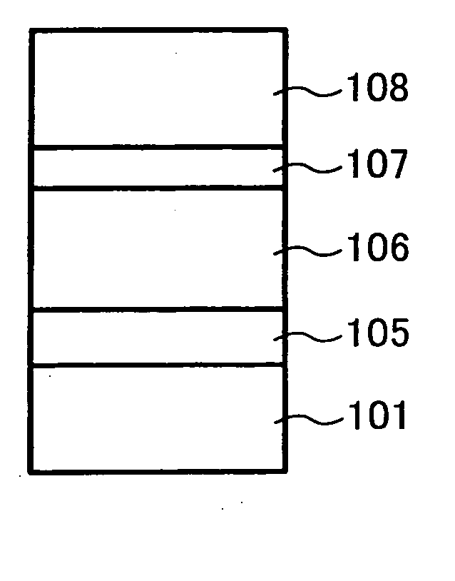
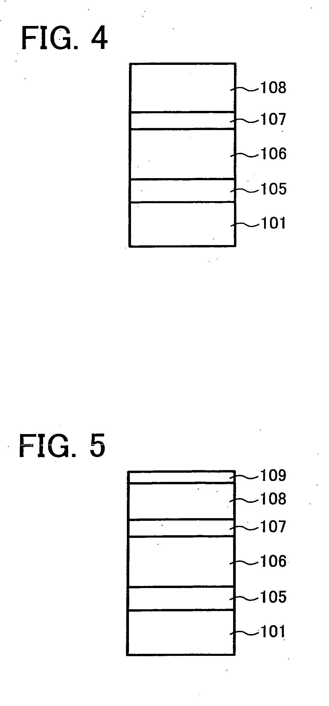
An image bearing member including an electroconductive substrate, a charge blocking layer disposed overlying the electroconductive substrate, a moire prevention layer disposed overlying the charge blocking layer, and a photosensitive layer disposed overlying the moire prevention layer. The charge blocking layer contains N-alkoxymethylized nylon and optionally at least one of an aliphatic dicarboxylic acid and an aliphatic tricarboxylic acid. The moire prevention layer contains a titanium oxide having a purity not less than 99.0% and a cross-linking resin.

Description

BACKGROUND OF THE INVENTION [0001] 1. Field of the Invention [0002] The present invention relates to an image bearing member, image forming apparatus and process cartridge. [0003] 2. Discussion of the Background [0004] Recently, image bearing members have been actively developed using organic photoconductive materials as photoconductive materials for use in image bearing members, which have advantages over inorganic materials such as Se, CdS and ZnO in terms of sensitivity, thermal stability and toxicity. Image bearing members formed of such organic photoconductive materials have been provided in a number of photocopiers and printers. When a photosensitive layer of an image bearing member formed of such organic photoconductive materials is formed, a function separation type in which a charge transport layer is accumulated on a charge generating layer is widely used because the function separation type has excellent sensitivity and durability. Generally, in an image forming apparatus...

Claims


Application Information

Patent Timeline
IPC IPC(8): G03G5/14
CPCG03G5/0514G03G5/0571G03G5/14G03G5/14791G03G5/144G03G5/14704G03G5/142
Inventor TODA, NAOHIROYAMASHITA, YASUYUKIORITO, TAKESHI
Owner RICOH KK
Learn More