Gas filled hollow core chalcogenide photonic bandgap fiber raman device and method

a technology of chalcogenide and hollow core, which is applied in the field of gas filled hollow core chalcogenide photonic bandgap fiber, can solve the problems of high peak power, in kilowatts, and still necessary to reach threshold, and achieve high efficiency, high efficiency, and high raman cross-section

Active Publication Date: 2006-11-09
THE UNITED STATES OF AMERICA AS REPRESENTED BY THE SECRETARY OF THE NAVY
View PDF16 Cites 21 Cited by
  • Summary
  • Abstract
  • Description
  • Claims
  • Application Information

AI Technical Summary

Benefits of technology

[0016] These and other objects can be attained by achieving high efficiency Raman fiber lasers and amplifiers in the spectrum region of about 1-15 microns by using stimulated Raman scattering in a gas filled hollow core infrared transmissive chalcogenide photonic bandgap glass fiber or structure to frequency shift a shorter wavelength pump beam to a longer Stokes beam. The use of a highly nonlinear glass, such as chalcogenide, in the infrared transmissive photonic bandgap fibers for Raman devices not only allows high efficiency Raman conversion due to the high Raman cross-section of the gasses but enables high average power sources in wavelength regions unreachable by current devices. By choosing a suitable pump wavelength, Raman devices can be utilized to generate or amplify light in the wavelength region of about 1-15 microns, which includes the fingerprint region.

Problems solved by technology

Note, however, that very high peak powers, in the kilowatts, are still necessary to reach threshold due to the large mode area, poor mode quality, and high losses of the dielectric waveguides.
At least two issues limit the applicability of silica-based photonic bandgap fibers in the infrared.
Practically, however, the finite number of hole layers, variations in hole periodicity and deformation of the air hole size and shape results in penetration of the mode field into the cladding.
This can result in significant loss for signals at wavelengths that are highly absorbed by the photonic bandgap glass matrix, and thus efficient Stokes conversion beyond the transmission window of silica is not possible.
Note, too, that propagation of high power pump or Stokes wave at these wavelengths can lead to heating and damage of the fiber.
While the bandwidth of this gap is large, it would not be large enough to allow a single Stokes shift of a near infrared pump from 1-2 microns to the mid-infrared.
This limits the applicability of silica-based gas filled hollow core bandgap fiber for infrared Raman lasers and the like.

Method used


Image

  • Gas filled hollow core chalcogenide photonic bandgap fiber raman device and method
  • Gas filled hollow core chalcogenide photonic bandgap fiber raman device and method
  • Gas filled hollow core chalcogenide photonic bandgap fiber raman device and method

Examples


example

[0047] The use of hydrogen iodide (HI) gas filled arsenic selenide (AsSe) Raman photonic bandgap fiber laser is demonstrated in this example.

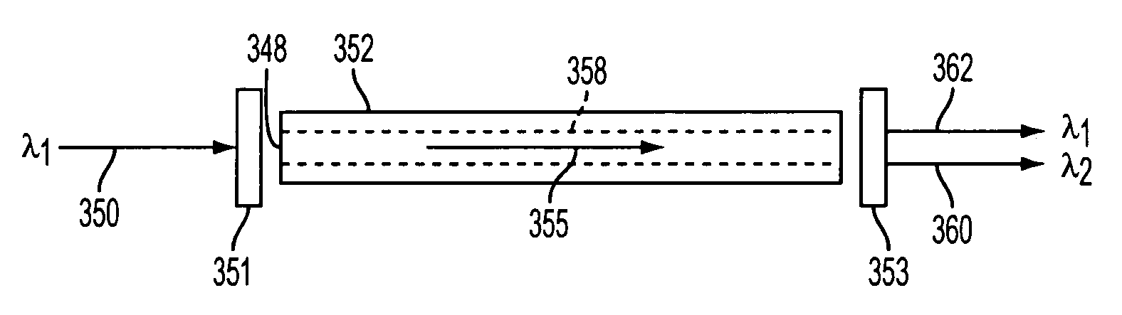
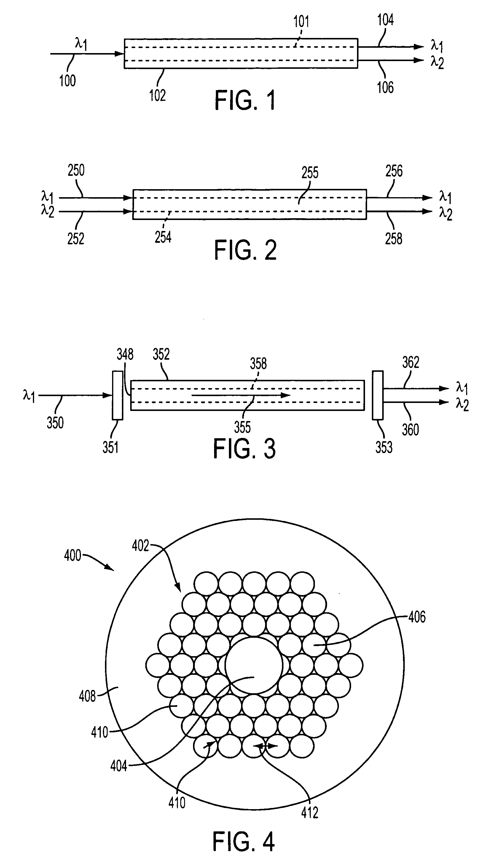
[0048] The hollow core gas filled Raman laser included a chalcogenide glass photonic bandgap fiber, cross-section of which is shown in FIG. 4, where the structured region 402 is 90% gas-filled with hydrogen iodide, an active Raman gas, contained in the fiber core. The hydrogen iodide was sealed in the arsenic selenide photonic bandgap fiber by silica capillary tubes which were capped with dielectric mirrors coated for appropriate wavelengths—high transmission at pump wavelengths and high reflectivity at the Stokes wavelength at the pump launch end and partial transmission at the Stokes wavelength at the input end. Inside of the hollow core photonic bandgap fiber was evacuated and backfilled with hydrogen iodide gas using the capillary manifold at the output end. Hydrogen iodide gas has vibrational Stokes shift of 2230 cm−1 and pump wavelength ...


PUM

PropertyMeasurementUnit
diameteraaaaaaaaaa
diameteraaaaaaaaaa
thicknessaaaaaaaaaa

Abstract

This invention pertains to a glass fiber, a Raman device and a method. The fiber is a hollow core photonic bandgap chalcogenide glass fiber that includes a hollow core for passing light therethrough, a Raman active gas disposed in said core, a microstructured region disposed around said core, and a solid region disposed around said microstructured region for providing structural integrity to said microstructured region. The device includes a coupler for introducing at least one light signal into a hollow core of a chalcogenide photonic bandgap fiber; a hollow core chalcogenide photonic bandgap glass fiber; a microstructured fiber region disposed around said core; a solid fiber region disposed around said microstructured region for providing structural integrity to said microstructured region; and a Raman active gas disposed in the hollow core. The method includes the steps of introducing a light beam into a hollow core chalcogenide photonic bandgap glass fiber filled with a Raman active gas disposed in the core, conveying the beam through the core while it interacts with the gas to form a Stokes beam of a typically higher wavelength, and removing the Stokes beam from the core of the fiber.

Description

BACKGROUND OF THE INVENTION [0001] 1. Field of the Invention [0002] This invention is characterized by a gas filled hollow core chalcogenide photonic bandgap fiber and its use. [0003] 2. Description of Related Prior Art [0004] In the Raman method, a photon interacts with a molecule and excites the molecule to a higher energy vibrational state. In the process, the incident photon loses energy and is converted to a lower frequency photon. Normally, this process converts a small fraction of the incident photons of the pump to lower frequency photons. The generated lower frequency photons are the Stokes wave. In stimulated Raman scattering, however, the Stokes wave is of high enough intensity to stimulate the scattering of other photons, resulting in the conversion of a large fraction of the pump beam to the Stokes beam. The frequency shift of the pump beam is dependent upon the vibrational or rotational modes of the molecules comprising the media. [0005] Raman conversion in highly nonl...

Claims


Application Information

Patent Timeline
Patent Type & Authority Applications(United States)
IPC IPC(8): G02B6/032
CPCC03B2201/86C03B2203/16C03B2203/42H01S3/302G02B6/02347G02B6/032H01S3/06741G02B6/02328
Inventor SHAW, L. BRANDONSANGHERA, JASBINDER S.AGGARWAL, ISHWAR D.THIELEN, PETER A.
Owner THE UNITED STATES OF AMERICA AS REPRESENTED BY THE SECRETARY OF THE NAVY
Why Eureka
Try Eureka