
Lighting unit, display device, and phosphor film

a technology of phosphor film and light conversion efficiency, which is applied in the direction of discharge tube luminescnet screen, lighting and heating apparatus, instruments, etc., can solve the problems of difficult to lengthen the lifetime of each of these phosphors, narrow color reproduction range, and low light conversion efficiency, and achieve long lifetime, wide color reproduction range, and high efficiency

Active Publication Date: 2006-11-16
DAWNCREST IP LLC
View PDF7 Cites 86 Cited by
  • Summary
  • Abstract
  • Description
  • Claims
  • Application Information

AI Technical Summary

Benefits of technology

[0013] In view of the foregoing, an object of the present invention is to provide a phosphor film and a lighting unit each of which: does not greatly affect the design of a light guide body; and has high efficiency, a long lifetime, and a wide color reproduction range.

Problems solved by technology

However, a conventional oxide phosphor has a problem in that light conversion efficiency is low.
The use of the so-called chalcogenide compound such as a sulfide, a selenide, or a telluride each having high light conversion efficiency for solving the problem involves the emergence of a new problem in that it is difficult to lengthen the lifetime of each of these phosphors owing to the poor moisture resistance of each of the phosphors.
In addition, a conventional lighting unit in which a conventional blue LED, and a green phosphor or a yellow phosphor are combined to provide white light has a problem in that a color reproduction range is narrow owing to a reduction in luminous intensity of a red color.
In addition, a conventional lighting unit in which a phosphor is applied to the rear surface of a light guide plate has a problem in that application conditions must be conformed every time the specifications of the light guide plate are changed because an application concentration must be conformed to a light intensity distribution inside the light guide plate.
Furthermore, applying the phosphor to the rear surface of the light guide plate involves the emergence of a problem in that it becomes difficult to design the light guide plate because light propagation property inside the light guide plate changes.
Furthermore, a conventional lighting unit in which a laminar wavelength converter is arranged between a light source and the light incidence plane of a light guide plate has a problem in that color mixing property is bad because a distance between the light source and the wavelength converter is so short that the intensity distribution of light applied to the wavelength converter is large.

Method used


Image

  • Lighting unit, display device, and phosphor film
  • Lighting unit, display device, and phosphor film
  • Lighting unit, display device, and phosphor film

Examples


example 1

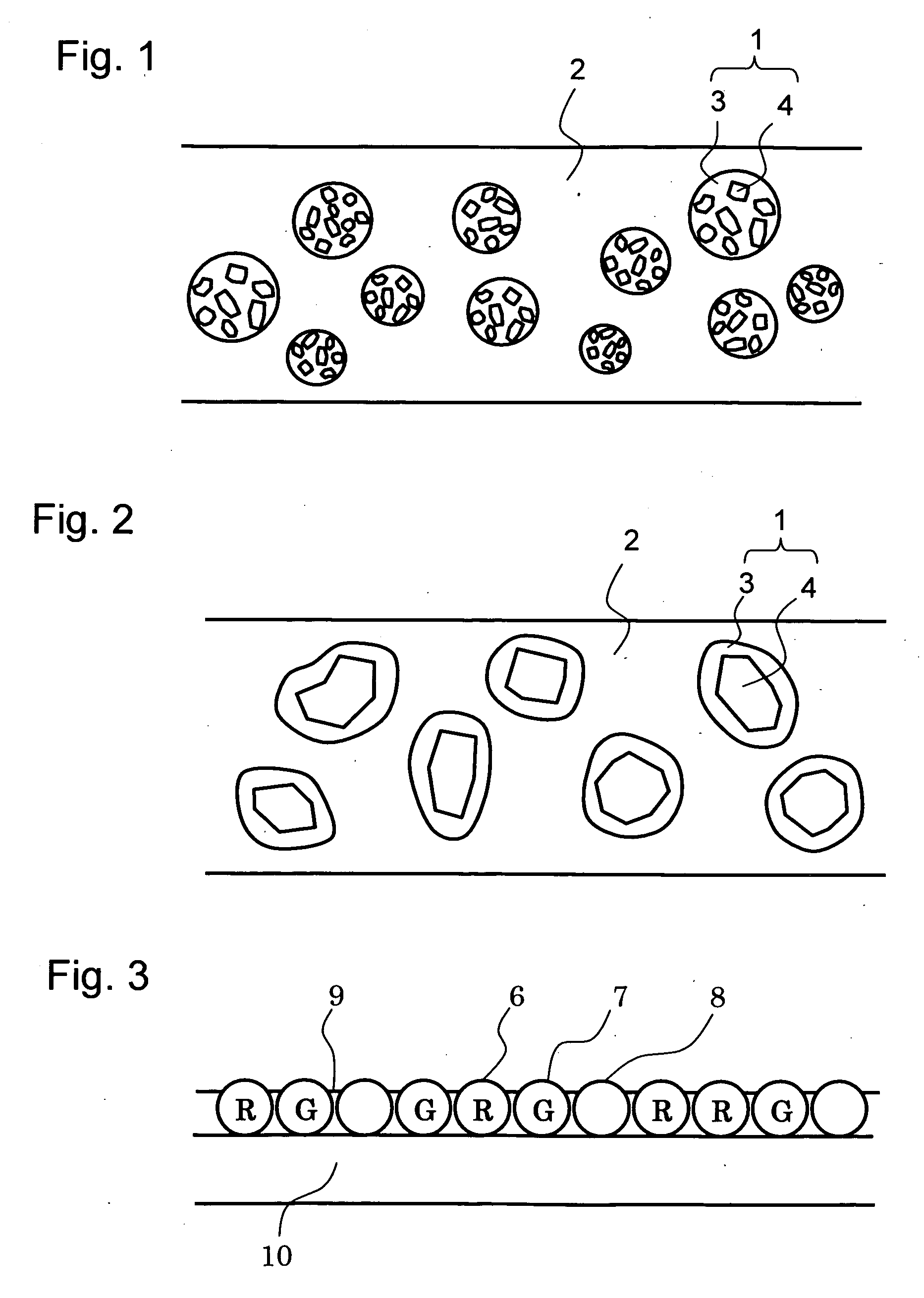
[0056]FIG. 1 is a sectional view schematically showing the constitution of a phosphor film of this example. As shown in the figure, phosphor beads 1 are mixed and dispersed into a transparent base material 2. Each of the phosphor beads 1 is formed by coating phosphor particles 4 with a water-impervious material 3, and is of a substantially spherical shape. At this time, the transparent base material 2 is of a film shape. A polymer material such as a silicone resin or a cycloolefin-based resin, or an inorganic material such as silicon dioxide or glass can be used as the water-impervious material 3. When the above inorganic material is used as the water-impervious material 3, the material 3 can be formed by growing the inorganic material around the phosphor particles 4 by means of a well-known sol-gel method. A polymer material such as an acrylic resin, a silicone resin, an epoxy resin, polycarbonate, or a cycloolefin resin, or an inorganic material such as silicon dioxide can be used...

example 2

[0059]FIG. 2 schematically shows the sectional constitution of a phosphor film of this example. This example is different from Example 1 in that any one of the phosphor particles 4 is coated with the water-impervious material 3. In this case as well, the same phosphor particles and water-impervious material as those of Example 1 can be used. In the case where any one of the phosphor particles 4 is coated with the water-imperious material 3, phosphor particles having a large average particle size (about 50 μm) can be used in forming the phosphor beads 1. The maximum particle size of many commercially available phosphor particles is about 10 to 50 μm, so the use of the phosphor beads of this example increases the degree of freedom in selection of materials for phosphor particles, and facilitates the design of a luminescent color.

[0060] In addition, the phosphor beads 1 each structured as shown in this example allow the cladding thickness of the water-impervious material 3 to be arbit...

example 3

[0062] Next, FIG. 3 schematically shows the sectional view of a phosphor film according to this example. In this example, red phosphor beads 6 and green phosphor beads 7 described in the above examples, and translucent beads 8 each containing no phosphor in it are simultaneously present on a transparent film 10 in such a manner that they bind together with the aid of a binder 9 to form a single layer. As in the case of Example 1 or 2, a mixing ratio among the phosphor beads is adjusted depending on the chromaticity of a luminescent color which one attempts to obtain through color mixing. The translucent beads 8 can be produced by means of a sol-gel method using a polymer resin such as a styrene resin or an acrylic resin, or an inorganic material such as silicon dioxide or glass.

[0063] The phosphor film of this is produced by, for example, applying a UV curable adhesive as the binder 9 to the transparent film 10 formed of a polyethylene resin, an acrylic resin, or a cycloolefin-base...


PUM


Abstract

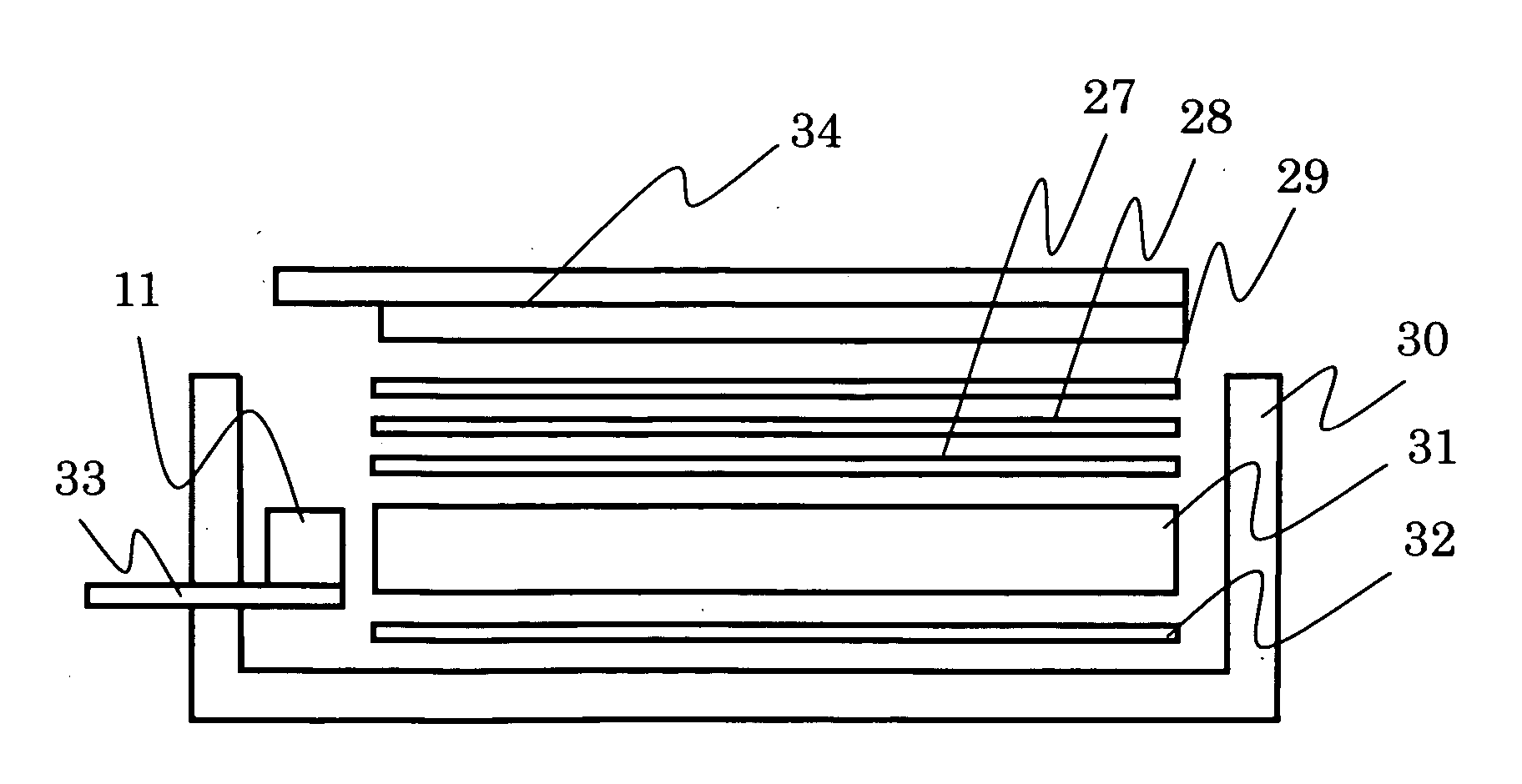
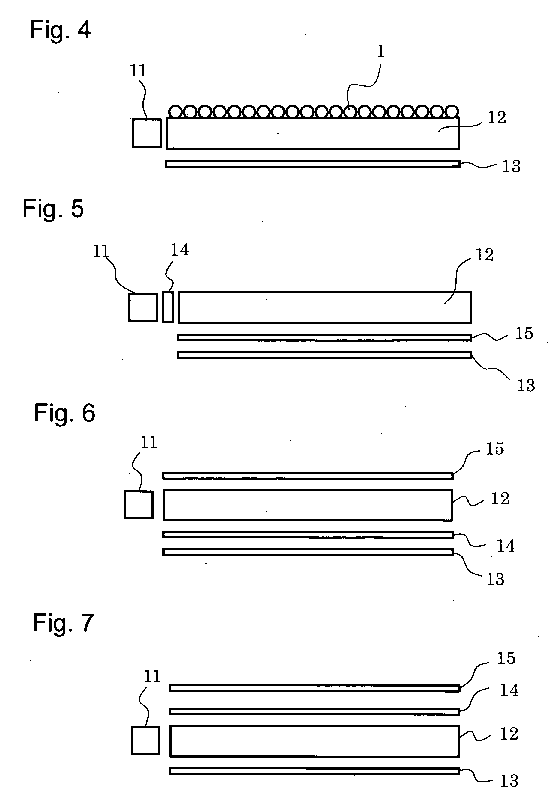
To provide a lighting unit which: does not greatly affect the design of a light guide plate; and has a long lifetime, high efficiency, and a wide color reproduction range by means of a phosphor. In view of the foregoing, the lighting unit of the present invention is constituted in such a manner that a phosphor bead or a phosphor film is arranged on at least one of the light irradiation plane of a light guide plate, the rear surface of the light guide plate, and the light incidence plane of the light guide plate. In addition, a phosphor film is constituted by using: a phosphor bead formed of a phosphor particle and a water-impervious material with which the phosphor particle is coated so that the particle is confined in the material; and a polymer film holding the phosphor bead.

Description

BACKGROUND OF THE INVENTION [0001] 1. Field of the Invention [0002] The present invention relates to a liquid crystal display device used for a portable information equipment, a portable phone, and the like, a lighting unit such as a front light or a back light for irradiating a non-self light emitting display element with light, and for a phosphor bead or a phosphor film for converting a wavelength of light from a light source. [0003] 2. Description of the Related Art [0004] Liquid crystal display devices providing high-definition color images at low power consumptions have been frequently used as display devices for recent portable phones, mobile computers, and the like. A light source employing a high-luminance white LED has been used as the light source for the lighting units, for illuminating liquid crystal devices used in those liquid crystal display devices. [0005] In particular, a bright reflection type liquid crystal display device or a double-side visible type liquid cryst...

Claims


Application Information

Patent Timeline
IPC IPC(8): H01J63/04H01J1/62
CPCG02B6/0023G02B6/004G02B6/0028G02F1/1335
Inventor DEJIMA, NORIHIROKURIHARA, MAKOTOFUKUDA, TOMOKI
Owner DAWNCREST IP LLC
Learn More