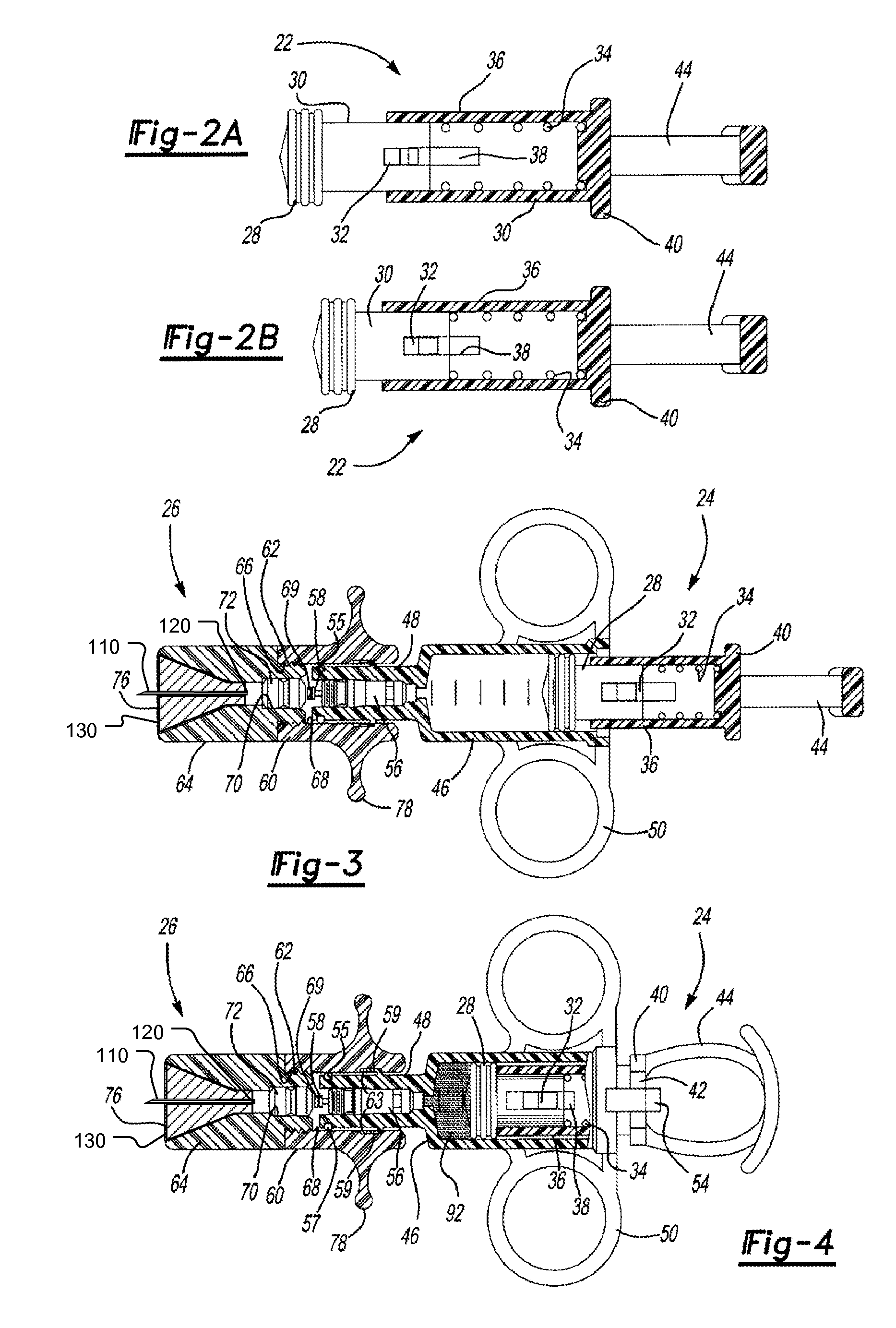
[0009] The medicament delivery device of this invention thereby separates the charging or pressurizing function from the use function. That is, the medicament delivery device of this invention may be utilized by a patient to first “arm” or pressurize the valve inlet and then deliver fluid under pressure to the housing chamber containing the
cartridge by opening the valve. Thus, for example, the patient may first arm the medicament delivery device of this invention by manipulating the pressure delivery device to pressurize a chamber at the valve inlet, then turn the device to receive the medicament conduit (needle,
mouthpiece or nosepiece) in the user's body and then open the valve to deliver a controlled unit
dose of a medicament to the
system of the patient through the conduit into the user's body. This simplifies the operation and use of the device to minimize
user error and consistently deliver a predetermined quantity or dose of medicament to the patient'
s system.
[0013] The
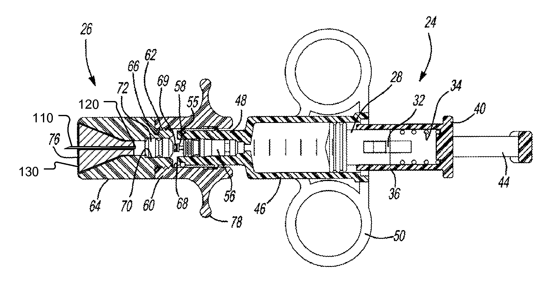
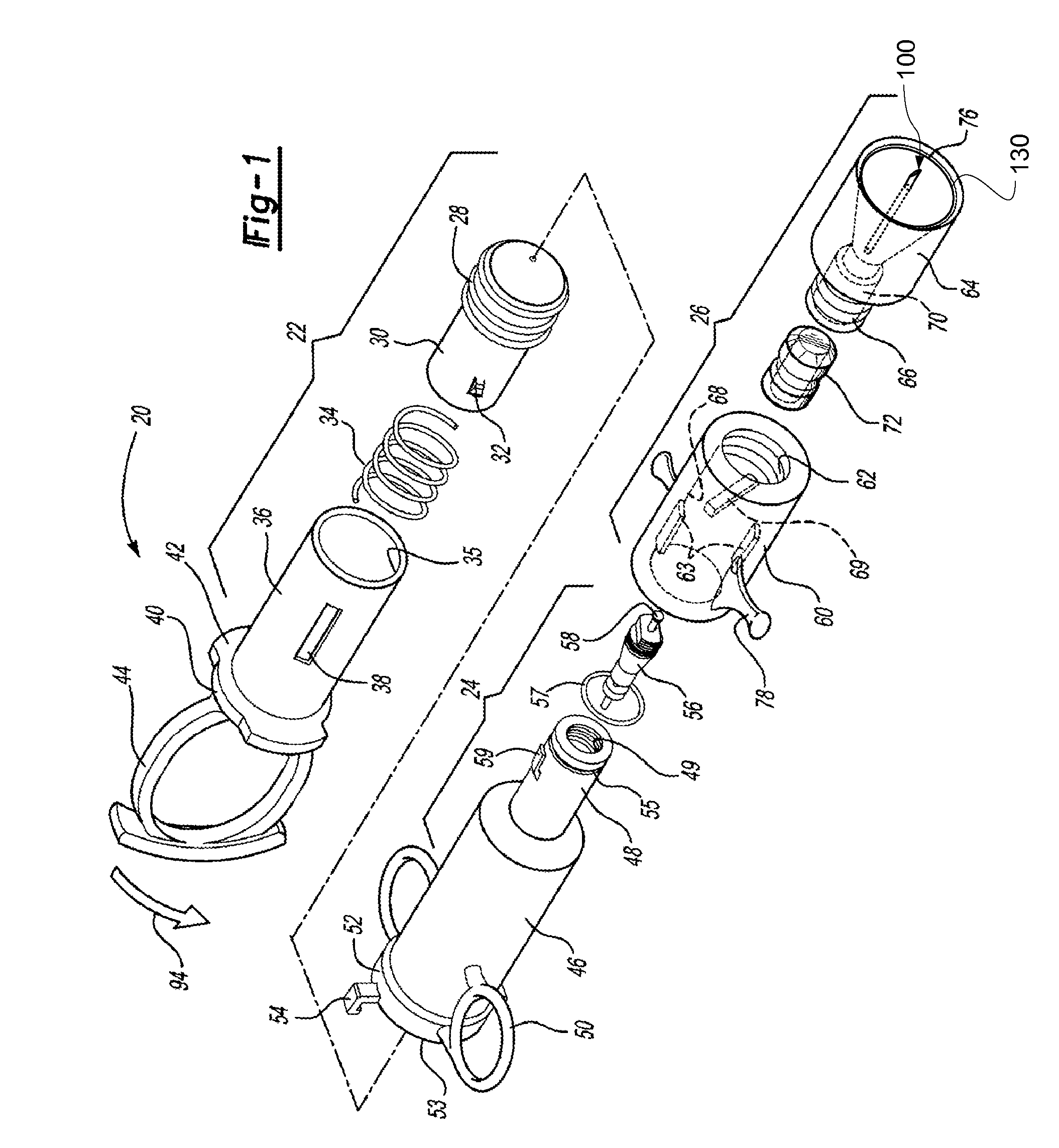
cartridge for the medicament delivery device of this invention is preferably simple in construction, inexpensive and disposable, such that the delivery device is reusable by inserting a new cartridge in the housing chamber following each use. However, the cartridge may be eliminated in a nonreusuable delivery device wherein the burstable membranes are provided at the inlet and outlet to the housing chamber. In the preferred embodiment of the medicament delivery device of this invention, the medicament cartridge includes a body having opposed ends, a passage through the body and through the opposed ends, a medicament stored in the passage and burstable or pierceable membranes covering and sealing the passage at the opposed ends of the body. In the preferred embodiments, the opposed ends of the cartridge body surrounding the passage are convex and the burstable membranes are stretched taut over the convex opposed ends and bonded thereto, sealing the passage. In the disclosed embodiment, the opposed ends of the body are frustoconical surrounding the passage and the membranes comprise a thin
polyolefin film heat-sealed or fused to the opposed frustoconical ends of the body. The term
polyolefin is understood to mean a
polymer containing olefin units such as, for example,
ethylene, propylene or 1-
butene units or any other alpha-olefin.
Polyolefin as used herein includes
polyethylene,
polypropylene,
ethylene- .alpha. olefin
copolymer, wherein the
alpha olefin having from 3 to 20, preferably 4 to 8 carbon atoms,
polyolefin copolymers made by polymerizing olefins in the presence of a
metallocene catalyst,
ethylene-
vinyl acetate copolymer, ethylene-
ethyl acrylate copolymer, and ethylene-
methyl acrylate copolymer. In particular, it is desirable to use
polyethylene, such as low-density, linear-low-density, very-low-density, medium-density, or high-density
polyethylene, or
polypropylene, such as a
polypropylene homopolymer, ethylene-propylene copolymer, or ethylene-propylene block copolymer.
[0014] In one preferred embodiment, the polymeric films which form the burstable membranes are preferentially or uniaxially oriented polyolefin films, preferably oriented polyethylene films, angularly related, wherein the films oriented on the opposed ends of the cartridge are most preferably oriented at approximately right angles. It has been found by the applicant that burstable membranes formed of preferentially or uniaxially oriented polyolefin film, most preferably polyethylene film, wherein the films are oriented at approximately right angles, results in improved delivery of the medicament from the body chamber of the delivery device to the
system of the user and results in a consistently greater emitted dose.
Polyolefin films can be oriented by drawing in one or both mutually perpendicular directions in the plane of the film to impart strength thereto using methods known in the art. Oriented polyolefin films include
machine direction and transverse direction orientation. Oriented polyolefin films include uniaxially or biaxially oriented films, with uniaxially films being preferred having a
draw ratio of at least 1.2. Uniaxially-oriented films have properties to their
advantage for use as the burstable membranes, including relatively
high stiffness, as indicated by the tensile modulus in a particular direction, usually the
machine direction, compared to the transverse direction. Properties of the oriented polyolefin film can be dependent to a certain degree on the particular
process conditions under which the polyolefin film was manufactured. For example, a stiffer film with lower transverse
burst pressure properties would result from an orientation process incorporating a larger
machine direction orientation
draw ratio. Thus, oriented polyolefins films can be tailored to provide an appropriate
burst pressure property within a preferred film thickness range.
[0016] In another preferred embodiment, the burstable membranes are formed of a cast polyolefin copolymer of polyethylene and polyethylene methylacrylate copolymer film having a thickness of about 0.5 mil, wherein the films are stretched taut over the passage and heat sealed or fused to the opposed ends of the cartridge. Where the burstable membranes are formed of preferentially or uniaxially oriented polyethylene film, the film preferably has a thickness of about 1 mil. However, it is believed that the burstable membranes may also be formed of other polymers including, for example, polypropylene, acetate,
polycarbonate, etc., wherein the film is preferably scored or embossed to reduce the required gas rupture pressure, thus having a rupture pressure of between 1.2 and 10 atmospheres, more preferably less than 5 atmospheres and most preferably between 1.5 and 4 atmospheres. Medicament cartridges employing such low burst pressure films allow for use of simple, manually actuated, pressurization mechanisms as described below. In the preferred embodiment of the cartridge for a medicament delivery device of this invention, the medicament passage or reservoir is generally cylindrical and the cartridge body is also generally cylindrical. An annular groove may be provided at the mid-portion of the body for ease of handling.
[0017] As disclosed in the above-referenced co-pending application, U.S. Ser. No. 09 / 879,517, the medicament cartridge utilized in the medicament delivery device of this invention may be formed by injection molding a generally cylindrical cartridge body having convex end portions and a passage through the end portions. The method then includes applying a thin burstable polyolefin sheet over one end, preferably by stretching a polyethylene sheet over the end and heat bonding the sheet to the convex end of the cartridge body, sealing the first end. The medicament may then be inserted through the open end of the passage and the second end is then sealed as described. Based upon computer modeling by the Applicant, the highest medicament delivery rate in a respiratory embodiment is achieved using one burstable polyolefin membrane at the exit of the delivery device. It would be expected that other embodiments would have similar results. This can be accomplished by the medicament delivery device of this invention by utilizing the
valve stem or another piercing member to pierce the burstable membrane at the inlet prior to or during actuation of the pressure member. However, in the disclosed preferred embodiment of the medicament delivery device, the opening of the valve substantially simultaneously bursts both the inlet and outlet membranes avoiding any loss of medicament through the inlet membrane during use.

