Device and method for manufacturing carbonated spring and carbonic water, control method for gas density applied thereto and membrane module

a technology of carbonated springs and carbonic water, applied in the direction of flow mixers, volume measurement, magnetic resonance measurement, etc., can solve the problems of increasing the amount of consumption of carbon dioxide gas, inability to secure the same carbon concentration, and the ability to add dioxide gas, etc., to achieve the effect of easy manufacturing

Inactive Publication Date: 2006-12-14
MITSUBISHI RAYON CO LTD
View PDF16 Cites 11 Cited by
  • Summary
  • Abstract
  • Description
  • Claims
  • Application Information

AI Technical Summary

Benefits of technology

[0075] Upon manufacturing of the artificial carbonated spring, the artificial carbonated spring having a desired carbon dioxide gas concentration can be manufactured easily by circulating the arti

Problems solved by technology

Meanwhile, the method by using the porous hollow yarn membrane has such a fear that the membrane turns hydrophilic due to a long term usage so that water leaks to the gas side to seal the membrane surface, thereby initial carbon dioxide gas adding ability is eliminated.
However, there is a fear that because water vapor which is water molecular passes, the passing water vapor is condensed on the gas side, thereby the condensed water (drain) seals the membrane surface.
However, according to this method, the drain release needs to be carried out frequently for a membrane in which the amount of passing vapor is large and thus, carbon dioxide gas charged on the gas side needs to be discharged into the atmosphere, and therefore, the amount of consumption of carbon dioxide gas is likely to be increased.
On the other hand, if the carbonated spring is produced according to the method by using the membrane, there is a disadvantage that the same carbon concentration cannot be secured each time although the carbonated spring having a high concentration can be obtained most highly effectively.
However, in case of carbonated spring in the vicinity of a carbon dioxide gas saturated concentration at 40° C., which is around 1200 mg/l, it has been made evident that in terms of its curative effect, a further remarkable effect can be expected and there is no way but changing a though that everything is satisfied if carbonated spring having an appropriate concentration is produced.
However, if such a method is applied, carbon dioxide gas is consumed wastefully, which is not preferable.
However, the circulation type has such a disadvantage that the time for producing the high-concentration carbonated spring is prolonged because no sufficient flow rate is secured in the initial period.
Further, this method has such a disadvantage that if alkali degree of raw water changes, no excellent reproduction can be attained.
However, according to the above-described gas measuring method, since its operation is very complicated and upon usage, it takes a large number of time and labor, the concentration of gas in a solution produced continuously from a di

Method used


Image

  • Device and method for manufacturing carbonated spring and carbonic water, control method for gas density applied thereto and membrane module
  • Device and method for manufacturing carbonated spring and carbonic water, control method for gas density applied thereto and membrane module
  • Device and method for manufacturing carbonated spring and carbonic water, control method for gas density applied thereto and membrane module

Examples


examples

[0167] Hereinafter, the present invention having the diversified embodiments will be described more specifically with reference to the examples.

[0168] First, an example of the carbon dioxide gas adding membrane module applied to the device of the present invention will be described specifically.

(Experiment No. 1)

[0169] With polymer blend composed of styrene base thermoplastic elastomer and polypropylene (made by DAI-NIPPON PLASTICS Co., Ltd., product name MK resin MK-2F (Tg=−35° C., composition ratio: (S)-(EB)-(S) tri-block copolymer 50 mass portion, composed of polymer (EB) obtained by hydrogenating styrene polymer (S) and butadiene polymer, as styrene base thermoplastic elastomer and atactic polypropylene 50 mass portion as polyolefin) as a material for a nonporous layer and polyethylene (made by TOSOH CORPORATION, product name: NIPORON HARD 5110) as a material for a porous layer, a three-layered composite hollow yarn membrane shown in FIG. 5 having the outside diameter of 300...

experiment no 4

(Experiment No 4)

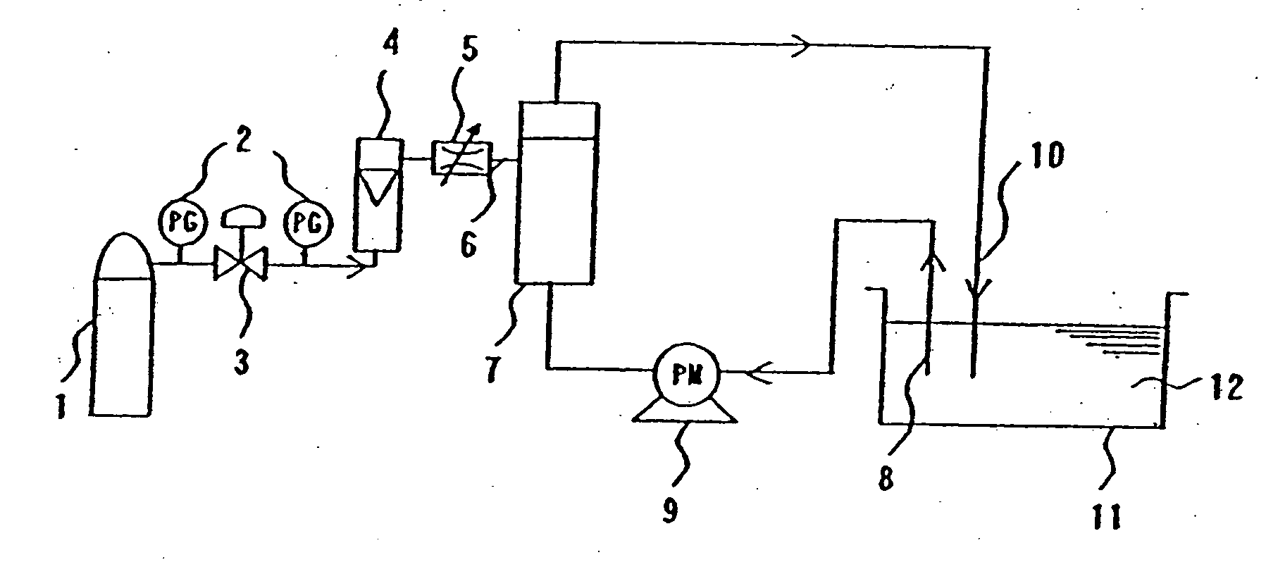
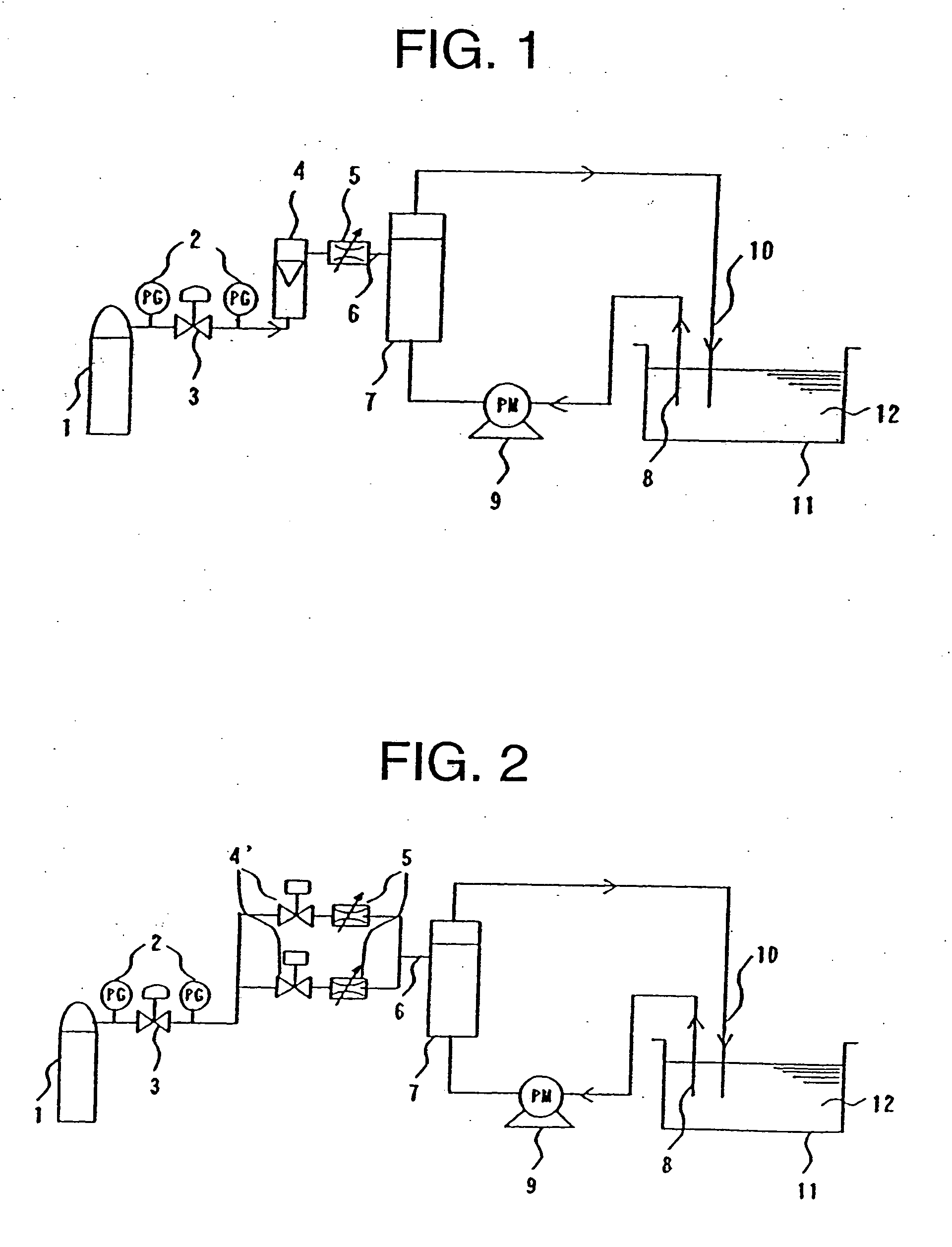
[0187] Carbonated spring was produced with the circulation type device shown in FIG. 1. The carbon dioxide gas pressure was controlled to 0.4 MPa with a pressure control valve As a flow meter, an electronic mass flow meter (CMS0020) made by Yamatake Hanewel Co., Ltd. was used and as a flow control valve, a mass flow control valve (MODEL 2203) made by KOFLOK K.K. was used to control the carbon dioxide gas flow rate to 1.0 l / min (converted under 20° C.) As a dissolver, non-used hollow yarn module product made with a three-layered composite hollow yarn membrane (made by Mitsubishi Rayon Co., Ltd.) whose membrane area was 0.6 m2 was used. Hot water at 40° C. was poured into the bath by 10 l and the hot water was returned to the bath by 5 l every minute by means of a suction pump.

[0188] Table 2 shows the result obtained 10 minutes after circulation. The first time in Table 2 indicates the result collected first in the experiment and the second time indicates the result ...

experiment no 7

(Experiment No 7)

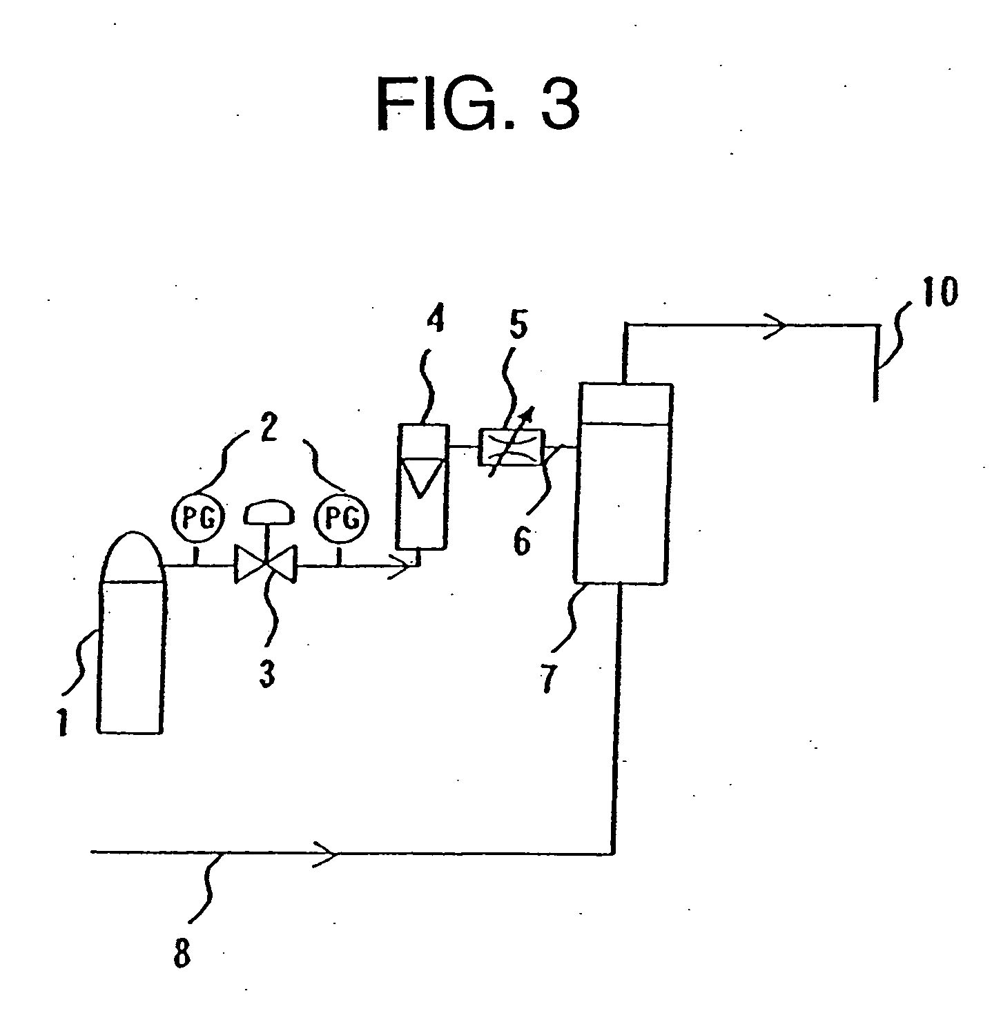
[0191] Carbonated spring was produced with the one-pass type device shown in FIG. 3. The carbon dioxide gas pressure was controlled to 0.4 MPa with the pressure control valve. With the electronic mass flow meter CMS0020 made by Yamatake Hanewel Co., Ltd. as a flow meter and the float controller MODEL 2203 made by KOFLOK K.K. as a flow control valve, the carbon dioxide gas flow rate was controlled to 5.0 l / min (converted under 25° C.).

[0192] A hollow yarn module produced with the three-layered composite hollow yarn membrane (made by Mitsubishi Rayon Co., Ltd.) whose membrane area was 2.4 m2 was used as a dissolver. Water at 40° was fed to the dissolver at 5 l / min. Table 3 shows the result thereof. Carbon dioxide gas concentration was stabilized about two minutes after water was fed first.

(Experiment No. 8)

[0193] The flow control valve of Experiment No. 7 was opened to control the carbon dioxide gas supply amount with a pressure. The pressure was controlled to 0.2...


PUM

PropertyMeasurementUnit
Temperatureaaaaaaaaaa
Fractionaaaaaaaaaa
Fractionaaaaaaaaaa

Abstract

Hot water (12) in a bath (11) is pumped up by a suction pump (9) and introduced into a carbon dioxide gas dissolver (7) through solution flow rate adjusting means (14) and then, poured into the bath (11). Carbon dioxide gas supplied from a carbon dioxide gas cylinder (1) is introduced into the carbon dioxide gas dissolver (7) through gas flow rate adjusting means (5). At this time, the quantity of bubbles existing in artificial carbonated spring in a take-out pipe (15) is measured with a measuring device (13), and the solution flow rate adjusting means (14), gas flow rate adjusting means (5) and the like are controlled by means of a control device (16) using a relational expression between a preliminarily set quantity of bubbles and carbon dioxide concentration to obtain a desired concentration of carbon dioxide gas in carbonated spring. Because the carbon dioxide gas flow control means (5) is provided between the carbon dioxide gas dissolver (7) and a carbon dioxide gas supply source, carbonated spring of a high concentration can be always manufactured even if the pressure of supplied carbon dioxide gas changes or the permeating performance of a membrane changes.

Description

TECHNICAL FIELD [0001] The present invention relates to a device and method for manufacturing carbonated spring and carbonic water. More specifically, the present invention relates to a device and method for manufacturing carbonated spring and carbonic water having a high concentration in order to always obtain a predetermined carbonic acid concentration effectively. Further, the present invention relates to a method for measuring the gas concentration of a gas dissolved solution obtained by dissolving gas into a liquid and a device for manufacturing the solution. More particularly, the present invention relates to a method for controlling the gas concentration in the solution manufactured continuously to a desired concentration and a device for manufacturing a preferable gas dissolved solution and a membrane module for dissolving gas into the liquid effectively. BACKGROUND ART [0002] Solution in which gas is dissolved is used for various kinds of application. If exemplifying carbon...

Claims


Application Information

Patent Timeline
IPC IPC(8): B01F3/04A23L2/54A61H33/02A61H33/14B01F5/04
CPCA23L2/54A61H33/60A61H2033/145B01F3/0446B01F3/04787B01F3/04985B01F15/0022B01F15/00344B01F2003/04404B01F2003/04858B01F2003/04893B01F2215/0052Y10S261/07A61M35/00A61H33/02A61M35/30B01F23/231244B01F23/232B01F23/236B01F23/2373B01F23/23762B01F23/29B01F35/2132B01F35/2211B01F2101/305
Inventor SAKAKIBARA, HIROKIOOYACHI, KENTASAKA, HIROSHI
Owner MITSUBISHI RAYON CO LTD
Why Eureka
Try Eureka