Investment cast, stainless steel chain link and casting process therefor

a technology of investment cast and chain link, which is applied in the direction of driving chains, separation processes, transportation and packaging, etc., can solve the problems of chain with significant limitations in ultimate strength and working load (6,000 pounds), chain suffers from rapid wear and loss of strength, and abrasion wear, so as to achieve more efficient manufacture of attachment links, prevent heat concentration and formation, and eliminate shrinkage and dimensional variations

Active Publication Date: 2006-12-21
HUMCKE MICHAEL W +1
View PDF26 Cites 21 Cited by
  • Summary
  • Abstract
  • Description
  • Claims
  • Application Information

AI Technical Summary

Benefits of technology

[0026] A further object of the present invention is to provide an investment casting process for a stainless steel chain link which employs heat dispersing elements within the mold to prevent heat concentrations and formation of stress risers within and about the chain boss and the chain barrel, and to eliminate shrinkage and dimensional variations within and between the chain pin holes.
[0027] Yet another object of the present invention is to provide an investment casting process for a stainless steel chain link which allows for casting multiple chain links at one time, and which permits the more efficient manufacture of attachment links.
[0028] Still a further object of the present invention is to provide an investment cast stainless steel chain link which is substantially less expensive to maintain and operate over a 20 year service cycle than other chain links previously used in wastewater and wastewater treatment.
[0029] In one aspect of the invention, an investment cast, stainless steel chain link is provided for chains used in water and wastewater treatment. The

Problems solved by technology

While this chain has a high initial ultimate strength and application working load (42,000 pounds and 4,200 pounds respectively), the chain suffers from rapid wear and loss of strength primarily from oxidation of the link material, chemical and biological induced corrosion, abrasive wear from contact with iron oxide fines (from corrosion within the chain link components), and from contact with grit and silica fines in the process streams.
While the plastic chain provides excellent service in most lightly loaded chain and scraper collection equipment and clarifiers, the chain has significant limitations with regard to ultimate strength and working load (6,000 pounds and 2,500 pounds respectively).
This often limits effective service for CS (chain and scraper) collector equipment applications 250 feet or less in length.
All plastic chain and plastic chain pin materials have little abrasion resistance which renders standard plastic chains vulnerable to severe abrasive attack, and makes them generally unsuitable for sustained grit collector service.
In some cases, the lack of abrasion resistance can also make plastic chain unsuitable for sustained cross collector service in rectangular collectors.
In addition, the higher load requirements for grit collectors and screening equipment are often well above the rated working load of this chain, and may even exceed the ultimate strength of the plastic chain causing frequent service outages and catastrophic equipment failures.
Plastic materials are susceptible to attack from ultraviolet radiation and sunlight, can become brittle in severe cold, and have a high coefficient of expansion and contraction due to seasonal air temperature variations, and variable ambient water temperature.
This make

Method used


Image

  • Investment cast, stainless steel chain link and casting process therefor
  • Investment cast, stainless steel chain link and casting process therefor
  • Investment cast, stainless steel chain link and casting process therefor

Examples


Embodiment Construction

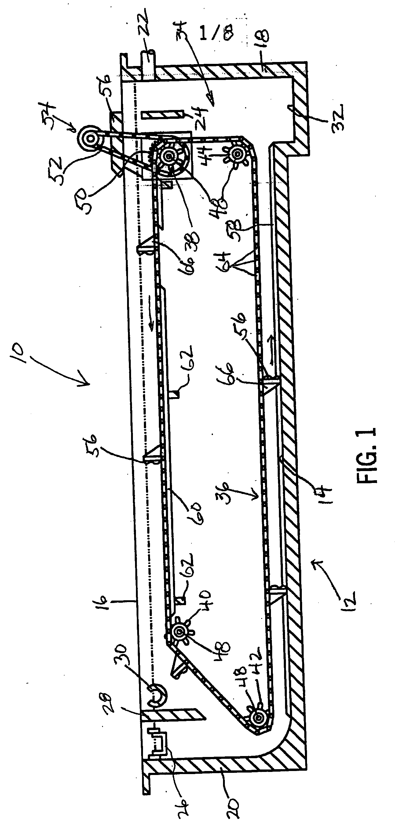
[0049] Illustrated in FIG. 1 is one type of a sediment removal or wastewater treatment apparatus 10 which embodies the chain construction of the invention, and which functions to remove waste material such as settlable solids or sludge, grit, trash, debris and floatable waste or scums from wastewater, although other liquids could be treated.

[0050] The wastewater treatment apparatus 10 includes a primary sedimentation or settling tank 12 which is usually formed with reinforced concrete or steel. The tank 12 includes a bottom 14, a pair of opposite sidewalls 16 (one is shown), an influent endwall 18, and an effluent end wall 20, which together defines the tank 12. A conduit 22 extends through the influent endwall 18 for delivering wastewater into the tank 12. A first baffle 24 extends across the top of the tank 12, between the sidewalls 16 and downwardly in front of and somewhat below the conduit 22 to minimize the movement and turbulance created by the influent flow to less than 1 f...


PUM

PropertyMeasurementUnit
Fractionaaaaaaaaaa
Fractionaaaaaaaaaa
Fractionaaaaaaaaaa

Abstract

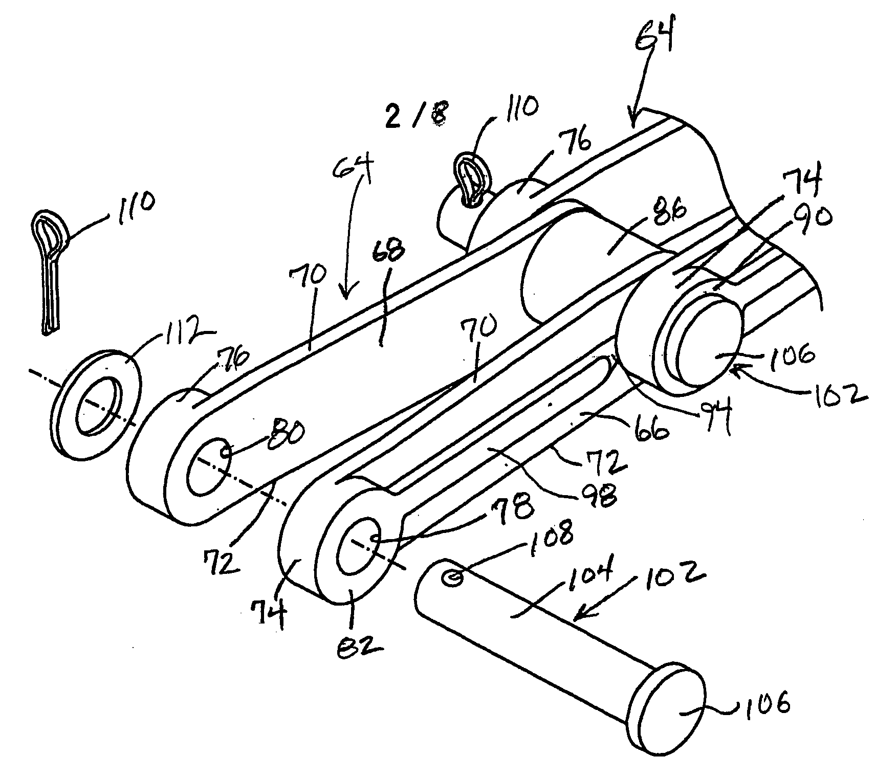
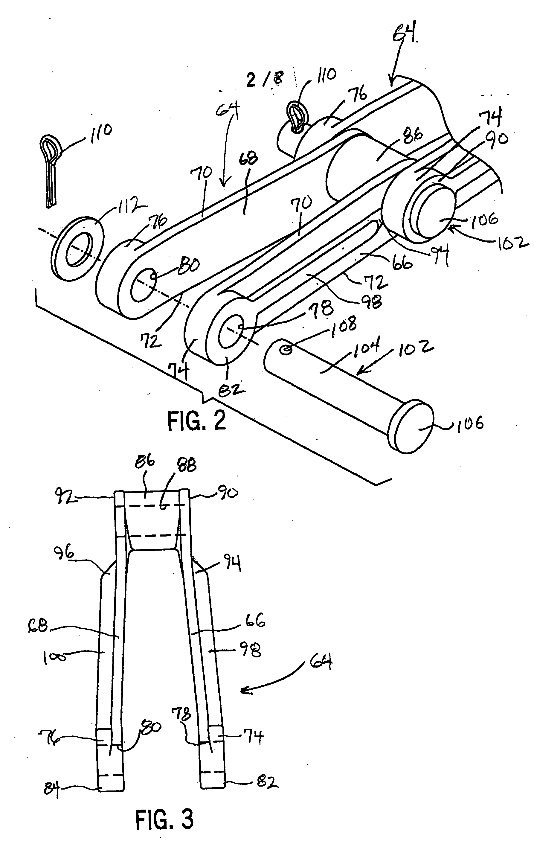
An investment cast, stainless steel chain link is provided for chains used in water and wastewater treatment. The chain link comprises a pair of spaced apart, elongated sidebars having forward ends and rearward ends. The forward ends are spread apart and are provided with outwardly and laterally extending bosses having transverse boss pin bores coaxially aligned with each other. The rearward ends are interconnected by a cylindrical barrel having a barrel pin bore extending through each of the sidebars. The sidebars are formed with outwardly and laterally projecting reinforcing ribs-extending between the bosses and the barrel pin bore along a substantial length of the sidebars. A freely rotatable chain pin is inserted through aligned boss and barrel pin bores from either end thereof for interconnecting first and second pairs of sidebars. An arrangement is provided for preventing the lateral dislodgement of the chain pin from the sidebars.

Description

FIELD OF THE INVENTION [0001] The present invention relates generally to chain constructions employed in water and wastewater conveyor type treatment systems and, more particularly, pertains to a stainless steel chain link produced in an investment casting process. BACKGROUND OF THE INVENTION [0002] Sludge, waste solids and scum collector mechanisms are commonly used in wastewater treatment tanks to remove debris and settled sludge from the bottom of collection tanks, to skim the floating grease and solids from the surface of collection tanks, and for removing grit and trash from wastewater and process streams. Typically, such collector and conveyor mechanisms include a pair of spaced apart continuously articulating chains trained over collector chain sprockets which are mounted on cross shafts supported on the sidewalls of the tank or equipment, and elongated transverse collector flights, scrapers and skimmers supported between the chains. One of the sprockets is driven so that the...

Claims


Application Information

Patent Timeline
IPC IPC(8): F16G13/06
CPCF16G13/07B01D21/18
Inventor HUMCKE, MICHAEL W.KRALLMAN, ANTHONY D.
Owner HUMCKE MICHAEL W
Why Eureka
Try Eureka