

Process for produicng stamper for direct mastering, and stamper produced by such process and optical disc
- Summary
- Abstract
- Description
- Claims
- Application Information
AI Technical Summary
Benefits of technology
Problems solved by technology
Method used
Image

Examples
first embodiment
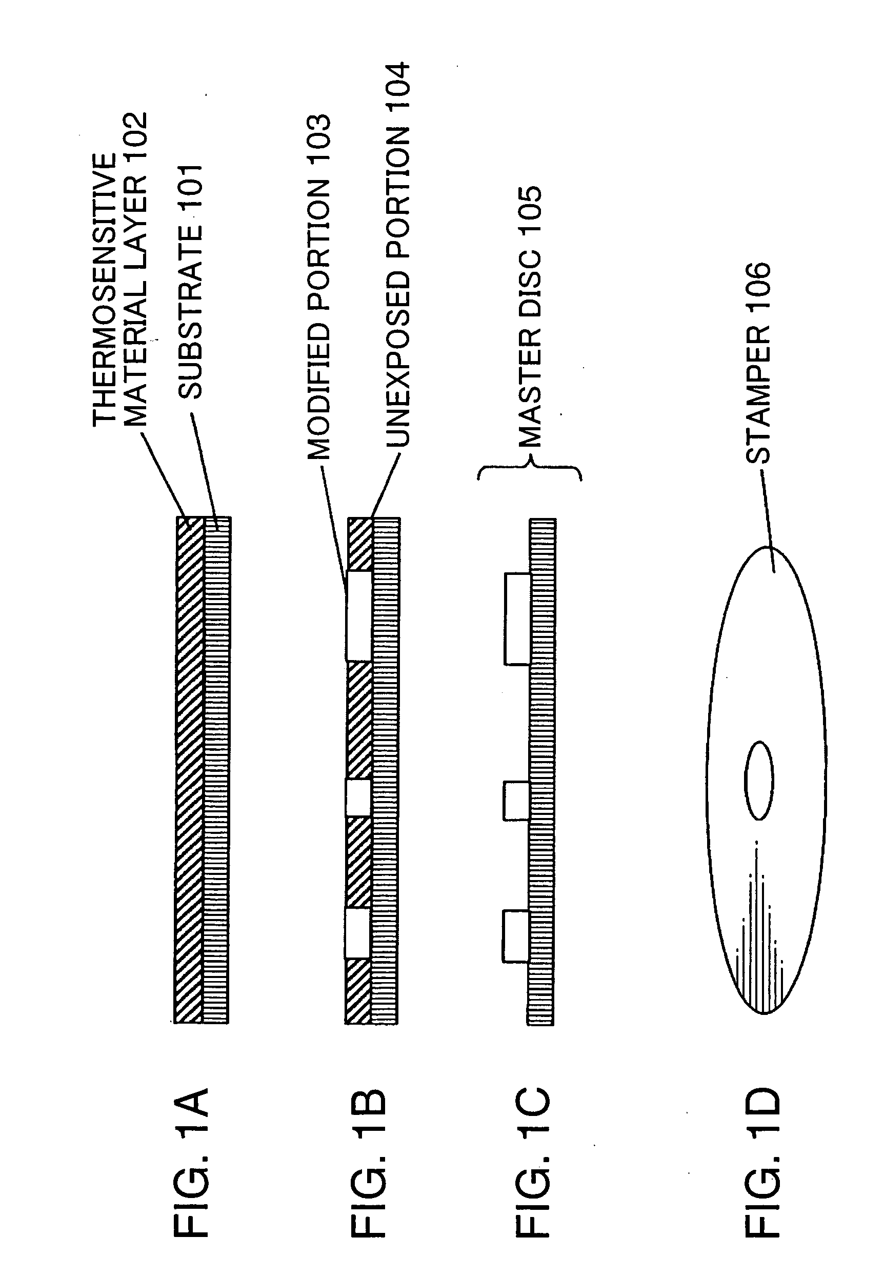
[0025] Referring to FIG. 1, a basic method for manufacturing a stamper of the present invention will be described. First of all, a process 1A of forming a thermosensitive material layer 102 onto a substrate 101 will be described. As the substrate 101, a metallic substrate, a silicon-based substrate, a glass substrate or the like may be used. As the metallic substrate, for example, the substrate made of at least one material of nickel, chromium, aluminum, titanium, cobalt, iron, molybdenum, tungsten, boron, copper, and tantalum as a main component, as well as being manufactured by mass-production at low cost, is used. These metallic substrates are preferable since a stamper having a thickness of the same level as of a stamper produced in a conventional mastering process is manufactured with ease. Further, as a silicon-based substrate, silicon compounds such as Si or SiO2, SiC, or the like are used. Since these compounds are widely utilized in a semiconductor field, they are relativel...
second embodiment
[0054] In the present invention, it is also a preferable embodiment that, in producing the stamper of the first embodiment, a heat-adjusting layer having low thermal conductivity is provided between the thermosensitive layer and the substrate. Hereinafter, the stamper to be produced according to this embodiment will be described: since the substrate, the thermosensitive material, and the like are same as those of the first embodiment, their descriptions will be omitted. In the present invention, the heat-adjusting layer means a layer disposed between the substrate and the thermosensitive material layer and capable of adjusting a heat amount provided by the laser beam to be used for modifying the thermosensitive material.
[0055] When molybdenum oxide or tungsten oxide is used as the negative-type thermosensitive material, the film temperature of the thermosensitive material layer elevates as the laser beam is irradiated, whereas the heat amount thereof is dispersed by thermal conduct...
third embodiment
[0069] In the present invention, the fine pits-and-bumps pattern may be formed on the substrate in the first embodiment.
[0070] Specifically, in the etching treatment, the pattern including the bump portions formed of the modified portions in the exposing step may be used as an etching mask. In the first embodiment, though the etching is stopped when the unexposed portions are etched(developed) by the etching treatment, the substrate may be further etched to form a fine pits-and-bumps pattern on the substrate as is conducted in the etching step utilized in a mastering method.
[0071] As the substrate to be used in such an embodiment, the same type of the substrate as of those employed in the above-described embodiments may be used; however, it is preferable to use a metal plate taking strength into consideration.
[0072] Hereinafter, the present invention will be specifically described by way of examples, and it should be noted that the present invention is not limited to these exampl...
PUM
 Abstract
Description
Claims
Application Information