Heart valve prosthesis and method of manufacture

Active Publication Date: 2006-12-28
AORTECH INT
View PDF13 Cites 118 Cited by
  • Summary
  • Abstract
  • Description
  • Claims
  • Application Information

AI Technical Summary

Benefits of technology

[0032] The leaflets are attached to the frame between posts, with a free edge which can seal the leaflets together when the valve is closed under back pressure. The leaflets are created in a mathematically defined shape allowing good wash-out of the whole leaflet orifice, including the area close to the frame posts, thereby relieving the problem of thrombus deposition under clinical implant conditions.
[0033] The leaflet shape has a second design feature, by which the pressure required to open the valve and the pressure gradient across the valve in the open position is reduced by creating a valve which is partially open in its stable unstressed position. Molding the leaflets in a partially open position permits them to open easily to a wider angle resulting in an increased effective orifice area, for any given polyurethane/elastomeric material. This permits the use of materials from a wider range of mechanical properties to fabricate the leaflets, including those of a relatively stiff nature, and also permits lower modulus materials to be incorporated as thicker and hence more durable leaflets, while retaining acceptable leaflet hydrodynamic function.
[0034] A third design feature is the reduction of a stress concentration i

Problems solved by technology

Dysfunction of one or more of these valves can have serious medical consequences.
Such dysfunction may result from congenital defects, or from disease induced damage.
A valve replacement operation is expensive and requires specialised facilities for open heart surgery.
Replacement of failed artificial heart valves carries increased risk over the initial replacement, so there are practical limits on the number of times reoperation can be undertaken.
Unfortunately, a patient who has had a mechanical valve implanted must be treated with anticoagulants, otherwise blood will clot on the valve.
Clotting on the valve can either restrict the movement of the valve opening member(s), impairing valve function, or can break free from the valve and obstruct blood vessels downstream from the valve, or both.
Unfortunately, tissue valves deteriorate over time, often as a result of calcification of the crosslinked natural tissue.
This deterioration presents a problem, particularly in young patients.
In third world countries, where rheumatic fever is still common, the problems of valve replacement in young patients are considerable.
Anticoagulants, required for mechanical valves, are impractical and accelerated calcification of tissue valves precludes their use.
This provides some restriction to flow, but more importantly, disturbs the blood flow patterns.
However, this valve design became unacceptably stenotic in small sizes.
This valve design used non-biostable polyurethane, which had tolerable mechanical durability, but which showed signs of polymer degradation after six months in vivo.
Current polyurethane valve designs have a number of potential drawbacks.
This region of stagnation is likely to encourage local thrombogenesis, with further restriction of the valve orifice in the longer term as well as increasing the risk of material embolising into the circulation.
Associated with the thrombosis may be material degradation (in non-biostable polyurethanes) and calcification resul

Method used


Image

  • Heart valve prosthesis and method of manufacture
  • Heart valve prosthesis and method of manufacture
  • Heart valve prosthesis and method of manufacture

Examples


first embodiment

1. First Embodiment of Heart Valve Prosthesis

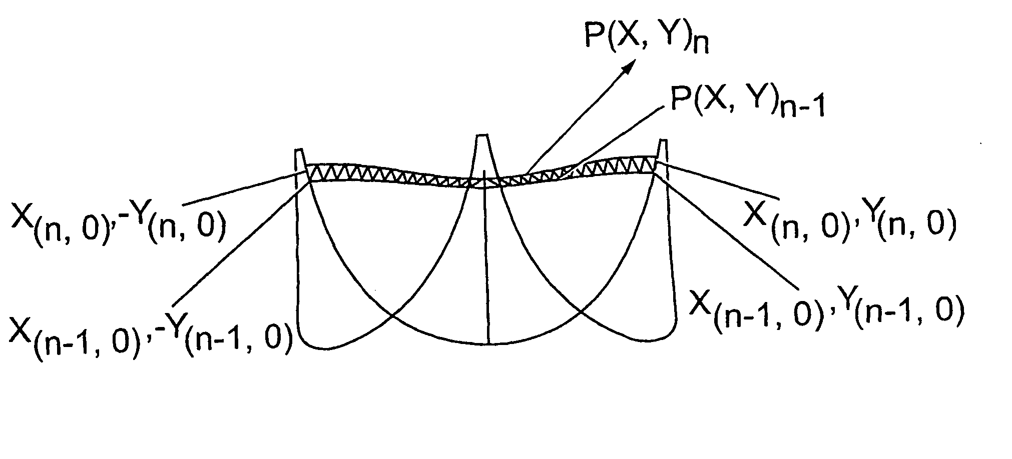
[0074] The following describes a particular way of designing a first embodiment of a valve of the present invention. Other different design methodology could be utilized to design a valve having the structural features of the valve disclosed herein. Five computational steps are involved in this particular method: [0075] (1) Define the scallop geometry (the scallop, 5, is the intersection of the leaflet, 2, with the frame, 1); [0076] (2) Geometrically define a valve leaflet in the closed position C; [0077] (3) Map and compute the distribution of area across the leaflet in the closed position; [0078] (4) Rebuild the leaflet in a partially open position P; and [0079] (5) Match the computed leaflet area distribution in the partially open or molded position P to the defined leaflet in the closed position C. This ensures that when an increasing closing pressure is applied to the leaflets, they eventually assume a shape which is equivalent to th...

example 1

[0131] The parameters described in the preceding sections are assigned the values set forth in Table 2 and are used to manufacture a symmetric valve. The included angle between adjacent leaflet free edges at the valve commissure for this valve is approximately 50°.

TABLE 2ParameterValue (mm)Closed positionZcO 0ZcO 0.0EcN(Z)EcN = 3.0.Z + 50.3EcO22.0EcJ20.0XT(Z) 0.0Partially-open positionθ12.7°EoJ50.0ZoO 4.0EoO51.8EoN27.7AuResult from iteration procedure finds thatAu varies from 1e−5 at the leaflet base to5.1 at 4 mm from the leaflet base to 3.8 atthe free edge.As(Y) 1.0BsResult from iteration procedure finds thatBs varies from 1e−3 at the leaflet base to1.6 at 3 mm from the leaflet base to 0.6 atthe free edge.

[0132]FIG. 12 shows the symmetric valve which is manufactured, using the values outlined in Table 1 and Table 2.

example 2

[0133] The parameters described in the preceding sections are assigned the values set forth in Table 3 and are used to manufacture an asymmetric valve. The included angle between adjacent leaflet free edges at the valve commissure for this valve is approximately 48°.

TABLE 3ParameterValue (mm)Closed positionZcO 0.0EcN(Z)EcN = 3.0.Z + 48.9EcO18.4EcJ20.0XT(Z)XT(n−1) = 0.97.(XT(n)) where XT(free edge) = 2.1Partially-open positionθ 7.1°EoJ50.0ZoO 5.0EoO51.5EoN29.0AuResult from iteration procedure finds thatAu varies from 1e−5 at the leaflet base to3.1 at 3 mm from the leaflet base to 2.2 at9 mm from the leaflet base to3.8 at the free edge.As(Y)Bs(Y) = (Y − c) / m where Bs = 1 at leaflet baseand m = 5.04 and c = −15.1 at leaflet freeedge.BsResult from iteration procedure finds thatBs varies from 1e−3 at the leaflet base to1.1 at 6 mm from the leaflet base to 0.4 atthe free edge.

[0134]FIG. 13 shows the valve which is manufactured using the values outlined in Table 1 and Table 3.

TABLE 4De...


PUM

PropertyMeasurementUnit
Angleaaaaaaaaaa
Angleaaaaaaaaaa
Angleaaaaaaaaaa

Abstract

A cardiac valve prosthesis having a frame and two or more leaflets (preferably three) attached to the frame. The leaflets are attached to the frame between posts, with a free edge which can seal the leaflets together when the valve is closed under back pressure. The leaflets are created in a mathematically defined shape allowing good wash-out of the whole leaflet orifice, including the area close to the frame posts, thereby relieving the problem of thrombus deposition under clinical implant conditions.

Description

[0001] This application is a continuation of U.S. application Ser. No. 10 / 165,204, filed Jun. 6, 2002, the contents of which are hereby incorporated herein by reference, which is a continuation in part of International Application Serial No. PCT / GB00 / 04673, filed Dec. 7, 2000, which International Application was published by the International Bureau in English as WO 01 / 41679 on Jun. 14, 2001.FIELD OF THE INVENTION [0002] The present invention relates to medical implants, particularly cardiac and vascular implants and prostheses. More specifically, the invention relates to a cardiac valve prosthesis comprising a frame and leaflets. Such valves may also be made without rigid frames and may also be used as valves in artificial hearts, whether the latter are intended for permanent implantation or for temporary support of a patient. BACKGROUND OF THE INVENTION [0003] In mammals the heart is the organ responsible for maintaining an adequate supply of blood, and hence of oxygen and nutrien...

Claims


Application Information

Patent Timeline
IPC IPC(8): B29C41/02A61F2/24
CPCA61F2/2415A61F2/2412Y10S623/90
Inventor O'CONNOR, BERNARDWHEATLEY, DAVID JOHNBERNACCA, GILLIAN MAUREENHAWORTH, WILLIAM STAFFORD
Owner AORTECH INT
Why Eureka
Try Eureka