

Display device, electronic device and method of driving display device
a display device and electronic technology, applied in the field of display devices, can solve the problems of difficult to form pixels for each color, and the organic layer is not deposited so well,
- Summary
- Abstract
- Description
- Claims
- Application Information
AI Technical Summary
Benefits of technology
Problems solved by technology
Method used
Image

Examples
embodiment mode 1
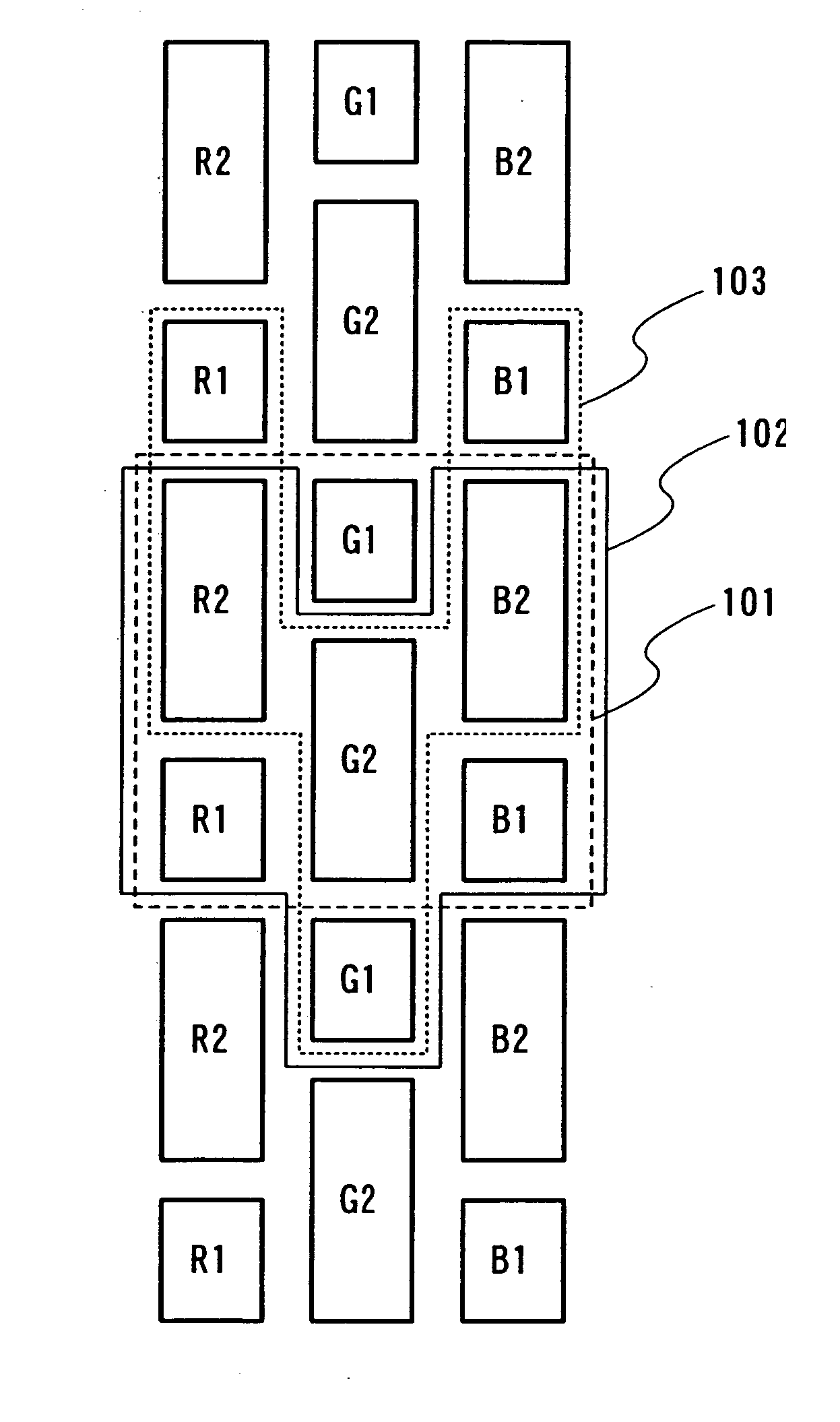
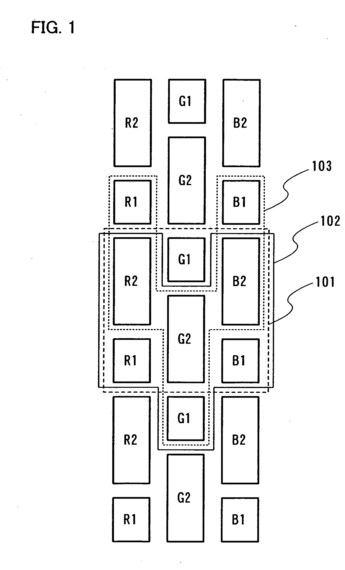
[0080]FIG. 1 shows a pixel configuration of three pixels. Usually, a region 101 corresponds to one pixel.
[0081] R1 and R2 constitute a red sub-pixel, G1 and G2 constitute a green sub-pixel, and B1 and B2 constitute a blue sub-pixel. One pixel is constituted by the sub-pixels of each color. Here, in R1 and R2, areas contributing to light-emission or displaying is set at R1 and R2=1:2. In G1 and G2, areas contributing light-emission or displaying is set at G1 and G2=1:2. In B1 and B2, areas contributing light-emission or displaying is set at B1 and B2=1:2. Gray scales can be expressed by selecting either, both or none of R1 and R2 so as to emit light (or contributes to displaying). In other words, an area gray scale method can be used. In FIG. 1, a square region (dot) surrounded by a heavy line is a display region constituting a part of a sub-pixel. The shape of this display region is not limited to that shown in FIG. 1. R1 is the smallest display region constituting a part of a red ...
embodiment mode 2
[0096] In Embodiment Mode 2, supply of a signal to each sub-pixel will be described. In FIG. 4, a signal line is arranged for each color and a gate signal line is arranged for each display region of each color. FIG. 4 corresponds to the structure in FIG. 1; however the present invention is not limited to this structure.
[0097] R2 at a second row is connected to a signal line 421 via a selecting transistor 401. R1 at a second row is connected to the signal line 421 via a selecting transistor 402 in other words, R1 and R2 are connected to the same signal line. R2 at a third row is also connected to the signal line 421 via a selecting transistor 403.
[0098] A gate signal line is connected to each selecting transistor. A gate signal line 411 is connected to the selecting transistor 401. A gate signal line 412 is connected to the selecting transistor 402. A gate signal line 413 is connected to the selecting transistor 403. By selecting each gate signal line sequentially, a signal can be ...
embodiment mode 3
[0104] Next, an example of a pixel circuit is shown. FIG. 6 shows a pixel of an organic EL. FIG. 6 represents a pixel circuit per one display region.
[0105] A selecting transistor 4904 which is a first transistor is controlled by using a gate signal line 4901 which is a first wire. When the selecting transistor 4904 is turned ON, a video signal is input into a storage capacitor 4905 from a source signal line 4902 which is a second wire. At this time, a driving transistor 4906 which is a second transistor is turned ON / OFF depending on the video signal, and a current flows to an opposite electrode 4908 through a light-emitting element 4907 from a power supply line 4903 which is a third wire.
[0106] Note that the selecting transistor 4904 of FIG. 6 corresponds to the transistors 401 to 403 of FIG. 4, and the transistors 501 to 503 of FIG. 5. In addition, the source signal line 4902 of FIG. 6 corresponds to the signal line 421 of FIG. 4 and the signal line 521 or 522 of FIG. 5.
[0107] N...
PUM
 Abstract
Description
Claims
Application Information