

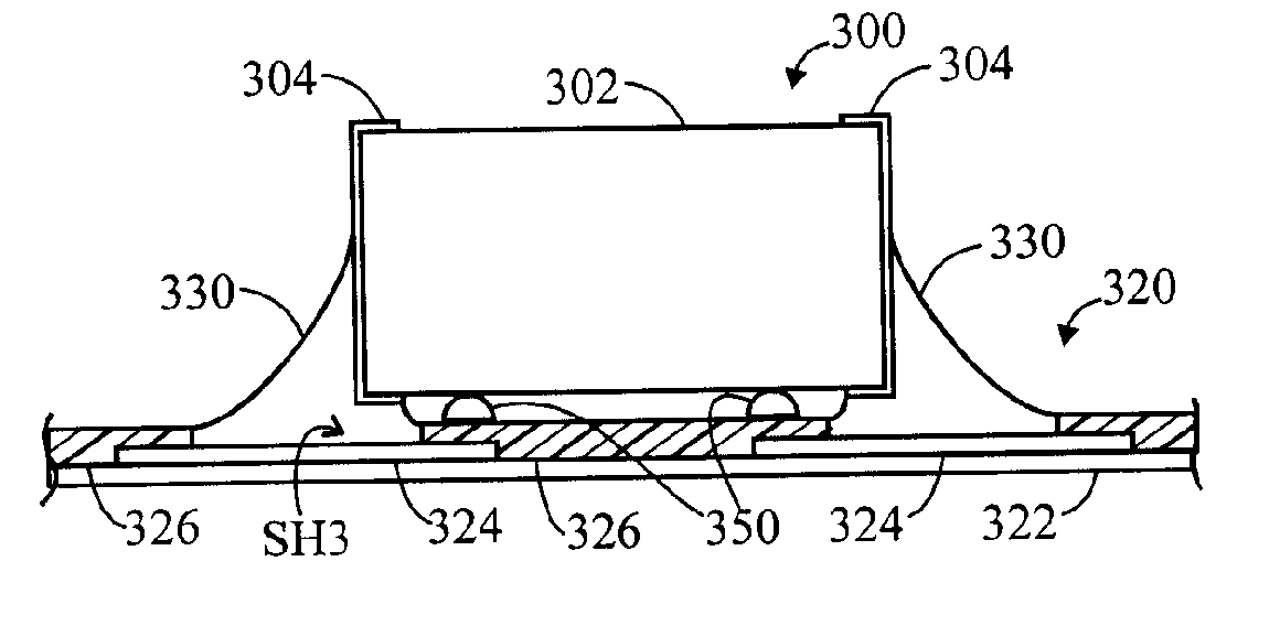
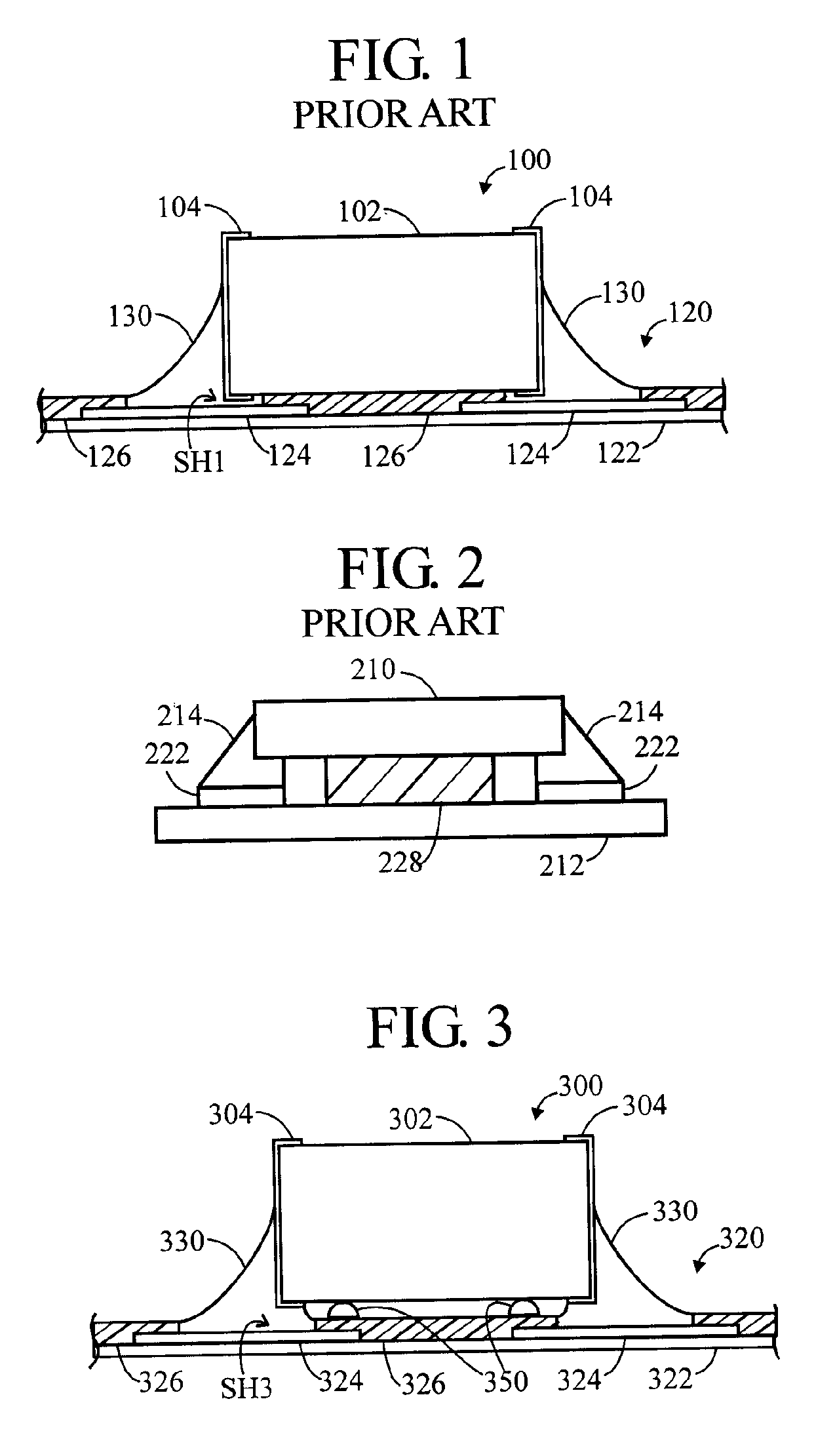
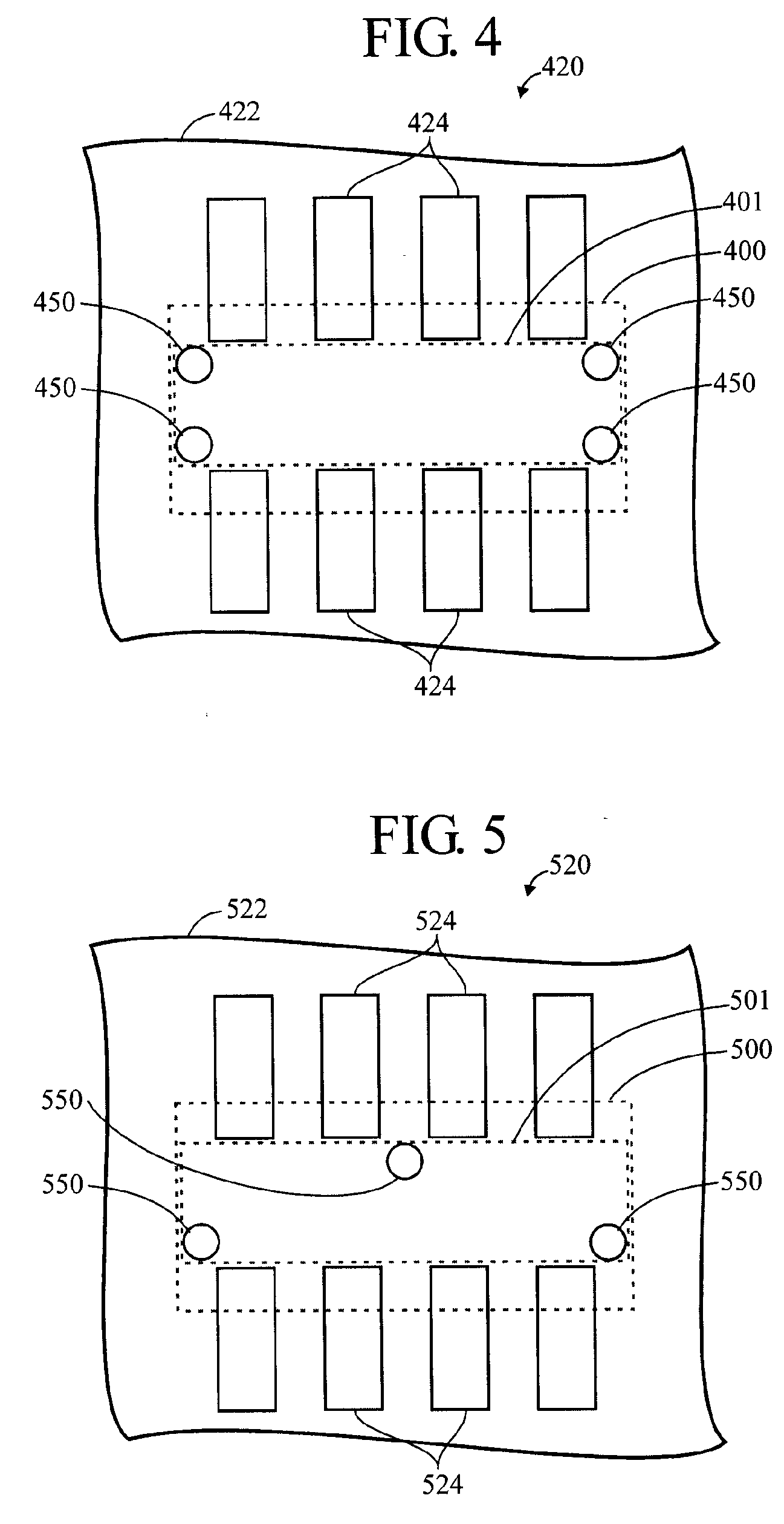
Standoff structures for surface mount components
a technology of surface mount components and standoff structures, which is applied in the direction of sustainable manufacturing/processing, final product manufacturing, soldering apparatus, etc., can solve the problems of limiting the reliability of assembled modules, high solder strain, and limiting the life of solder fatigue, so as to improve the thermal cycle fatigue life of multi-terminal capacitor solder joints, improve the reliability of surface mount interconnects, and increase volume
- Summary
- Abstract
- Description
- Claims
- Application Information
AI Technical Summary
Benefits of technology
Problems solved by technology
Method used
Image

Examples
Embodiment Construction
[0060] In the description that follows, numerous details are set forth in order to provide a thorough understanding of the present invention. It will be appreciated by those skilled in the art that variations of these specific details are possible while still achieving the results of the present invention. Well-known processing steps are generally not described in detail in order to avoid unnecessarily obfuscating the description of the present invention.
[0061] In the description that follows, exemplary dimensions may be presented for an illustrative embodiment of the invention. The dimensions should not be interpreted as limiting. They are included to provide a sense of proportion. Generally speaking, it is the relationship between various elements, where they are located, their contrasting compositions, and sometimes their relative sizes that is of significance.
[0062] In the drawings accompanying the description that follows, often both reference numerals and legends (labels, te...
PUM
| Property | Measurement | Unit |
|---|---|---|
| Height | aaaaa | aaaaa |
| Height | aaaaa | aaaaa |
| Height | aaaaa | aaaaa |
Abstract
Description
Claims
Application Information