Application of visbreaker analysis tools to optimize performance

a technology of visbreaker analysis and optimization tools, applied in hydrocarbon oil cracking process, thermal non-catalytic cracking, instruments, etc., can solve the problems of high instability of tar, insufficient supply of prior art systems, and severe fouling threat of particulate matter to energy recovery devices, etc., to maximize the production of light streams, improve the yield of light streams, and improve the effect of reproducibility

Active Publication Date: 2007-01-11
BL TECH INC
View PDF10 Cites 18 Cited by
  • Summary
  • Abstract
  • Description
  • Claims
  • Application Information

AI Technical Summary

Benefits of technology

[0009] In one aspect, the present invention provides a system and method for estimating a concentration of inhomogeneities contained within a tar byproduct of visbreaker operations. The invention does so by measuring the modulation of transmitted light through a fluid sample. The system uses a strongly convergent optical lens system to focus light onto a prepared sample. In one exemplary embodiment, the optics of a conventional optical microscope are used. A 3-dimensional translation stage is installed downstream of the focusing optics so that the sample can be scanned over a large region, and at a specific focal plane. A photo detector is placed on the opposite side of the stage from the focusing optics to measure the transmitted light through the sample. The photodetector is read-out by an analog-to-digital converter (ADC) in order to provide a digital (i.e., quantitative) measure of the transmitted light intensity. The translation stages are then moved in a pattern, such that the intensity of the transmitted light is measured over a representative path across the sample. When an opacity, scatterer or opaque particle of a threshold size is encountered in the sample, the intensity of the transmitted light is strongly attenuated. Such change of light intensity is then c

Problems solved by technology

While increasing this temperature arbitrarily will serve to drive the conversion rate higher, it also comes at the cost of producing a highly unstable tar as a precipitate in the process, with a high concentration of asphaltene particulates.
This particulate matter constitutes a severe fouling threat to the energy recovery devices (i.e. furnace and heat exchangers) in the process.
While it is k

Method used


Image

  • Application of visbreaker analysis tools to optimize performance
  • Application of visbreaker analysis tools to optimize performance
  • Application of visbreaker analysis tools to optimize performance

Examples


Embodiment Construction

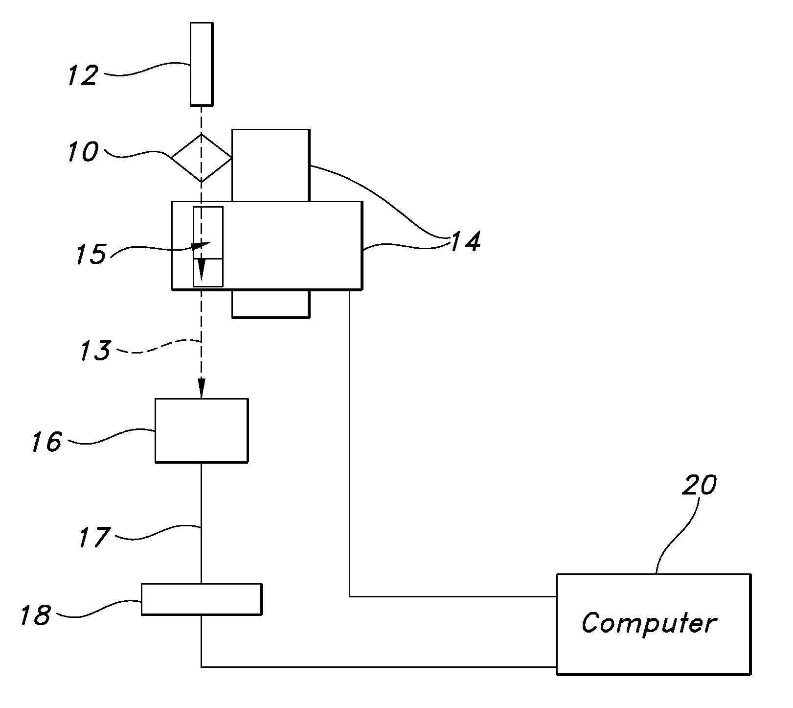
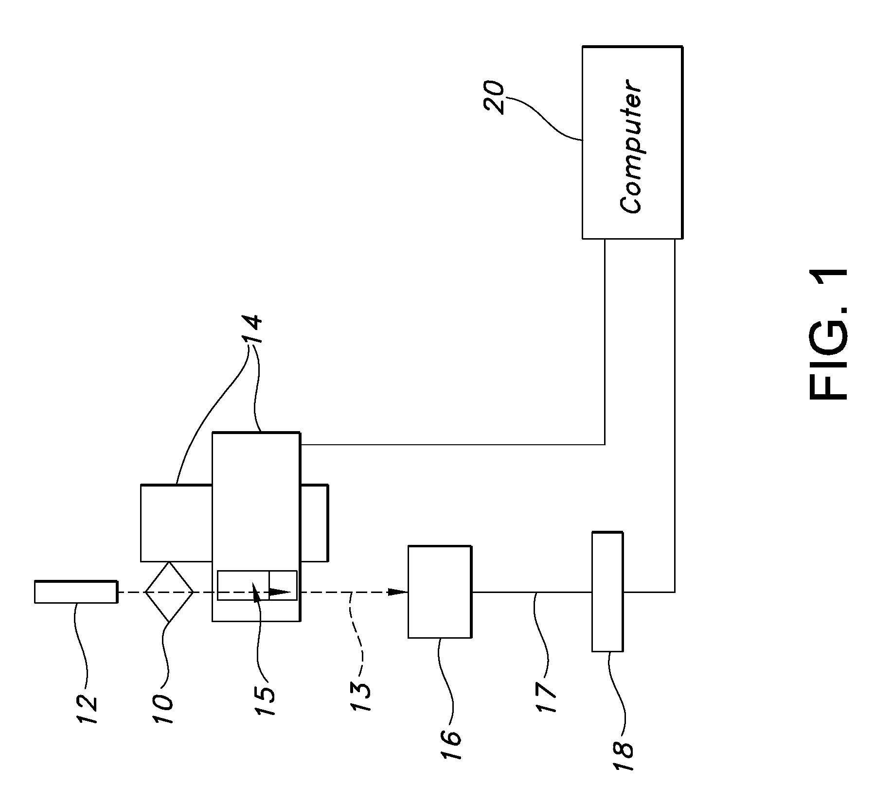
[0027] Exemplary embodiments and examples describing the present invention will be described below with reference to the accompanying drawings. As shown in FIG. 1, this invention uses an optical system as generally indicated by the number 10, which in the present exemplary embodiment comprises a convergent lens, a light source 12, and a multi-axis translation stage 14. The light source 12 may be implemented, for example, in the form of a solid state visible laser. An infra-red (IR) laser may also be used, and is in some cases preferable owing to the fact that HC solutions are typically much more transparent to IR light, than visible light. The translation stage 14 may be moved horizontally in the x and y directions in response to control signals generated by an associated computer 20 to direct the light beam along a plurality of paths through the sample. The third axis moves the stage vertically, towards and away from the focusing lens. This permits selection of a focal plane within...


PUM


Abstract

A system and method for quantifying opaque inhomogeneities within a fluid sample. The system uses an optical lens system to focus a light beam onto a stage where the sample is introduced. The light beam is directed onto the sample in a pattern such that the intensity of transmitted light is measured as a function of path length. A photo detector measures the transmitted light through the sample. Fluctuations in transmitted light intensity are then correlated with detection of opaque inclusions in the sample. The system also includes an automated program which utilizes these optical concentration measurements to determine the fouling potential of visbroken tars, and regulates the introduction of chemical inhibitors into a visbreaker unit to improve the yield of light streams and/or economic value of product.

Description

CROSS REFERENCE TO RELATED APPLICATION [0001] This application is a continuation-in-part of U.S. patent application Ser. No. 11 / 178,846 filed Jul. 11, 2005.FIELD OF THE INVENTION [0002] The present invention relates to systems and methods for characterizing and quantifying a dispersive medium; specifically, measuring the concentration of particles or the tendency toward forming a dispersed phase within a fluid sample. The present invention also provides a program which uses these measurements of concentration to monitor and control operation of a visbreaker unit to improve the yield of light streams. BACKGROUND OF THE INVENTION [0003] Thermal conversion is a process in which, by the application of heat, large hydrocarbon molecules are broken into smaller molecules with a lower boiling point. These operations are carried out in the industry of crude oil refining by plants such as a visbreaker, coker, and hydrocracker for obtaining intermediate or light cuts of higher value, from heav...

Claims


Application Information

Patent Timeline
IPC IPC(8): G01N21/00
CPCC10G9/007G01N15/0612G01N21/05G01N2021/0346G01N21/534G01N21/5911G01N33/28G01N21/51
Inventor VANHOVE, ANDREMORRIS, TIFFANY N.GOLIASZEWSKI, ALAN E.LASIUK, BRIAN W.VINCIGUERRA, DONATO
Owner BL TECH INC
Why Eureka
Try Eureka