Method and apparatus for coating medical implants

a technology for medical implants and coatings, applied in coatings, spraying apparatus, filament/thread forming, etc., can solve the problems of reducing the mechanical and tensile strength of the graft, the inability of the stent to prevent late restenosis, and the difficulty in producing polymer fiber shells suitable for vascular grafts, etc., to achieve the effect of reducing non-uniformities

Inactive Publication Date: 2007-02-08
NICAST LTD
View PDF99 Cites 136 Cited by
  • Summary
  • Abstract
  • Description
  • Claims
  • Application Information

AI Technical Summary

Benefits of technology

[0144] According to still further features in the described preferred embodiments the subsidiary electrode serves for reducing non-uniformities in the first electric field.

Problems solved by technology

Nevertheless, clinical data indicates that stents are usually unable to prevent late restenosis beginning at about three months following an angioplasty procedure.
Production of polymer fiber shells suitable for use as vascular grafts is particularly difficult, since such grafts must withstand high and pulsatile blood pressures while, at the same time, be elastic and biocompatible.
However, increasing the porosity of vascular grafts leads to a considerable reduction of the mechanical and tensile strength of the graft, and as a consequence to a reduction in the functionality thereof.
Such structural fiber formation considerably reduces the radial tensile strength of a spun product, which, in the case of vascular grafts, is necessary for withstanding pressures generated by blood flow.
However, such methods suffer froth the above inherent limitations which limit the use thereof when generating intricate profile fiber shells.
Hence, although electrospinning can be efficiently used for generating large diameter shells, the nature of the electrospinning process prevents efficient generation of products having an intricate profile and / or small diameter, such as vascular grafts.
In particular, since porosity and radial strength are conflicting, prior art electrospinning methods cannot be effectively used for manufacturing vascular grafts having both characteristics.
Although this device has been successful at sealing aneurysms and perforations, it is a bulky device with a significantly larger crossing profile and reduced flexibility compared to a state-of-the-art stent.
In addition, incorporation of drugs into the polymer in a sufficient concentration so as to achieve a therapeutic effect typically reduces the efficiency of the electrospinning process and causes different defects of the coating.
Still in addition, drug introduction into a polymer reduces the mechanical properties of the resulting coating.
Although this drawback is somewhat negligible in relatively thick films, for submicron fibers this effect may be adverse.
With respect to the above requirements, the properties of prior art stent coats are far less than satisfactory.
In addition, in prior art electrospinning systems electrostatic repulsion between fibers results in increased opening angle of the jet, an expanded sedimentation area and low rupture strength.
In percutaneous coronary intervention (PCI), including balloon angioplasty and stent deployment, there is a risk of vessel damage during stent implantation.
When the stent is expanded radially in the defective site, the plaques on the wall of the artery cracks and sharp edges thereof cut the surrounding tissue.
This causes internal bleeding and a possible local infection, which, if not adequately treated, may spread and adversely affect other parts of the body.
Local infections in the region of the defective site in an artery do not lend themselves to treatment by injecting an antibiotic into the blood stream of the patient, for such treatment is not usually effective against localized infections.
However, such one-shot treatment is not sufficient to diminish infections, and it is often necessary to administer antibiotic and / or other therapeutic agents for several hours or days, or even months.
However, U.S. Pat. No. 5,948,018 fails to address injuries inflicted by the stent in the course of its implantation on the delicate tissues of the artery.
These injuries may result in a local infection at the site of the implantation, or lead to other disorders which, unless treated effectively, can cancel out the benefits of the implant.
Prior art technologies, however, suffer from poor radial strength or having unsuitable porosity for being implanted in the body.
Additionally, prior art technologies fail to provide a method of coating a medical implant while being mounted on a delivery system, such as a catheter balloon.

Method used


Image

  • Method and apparatus for coating medical implants
  • Method and apparatus for coating medical implants
  • Method and apparatus for coating medical implants

Examples


example 1

[0313] A polycarbonate resin grade Caliper, 2071 was purchased from Daw Chemical Co. This Polymer is characterized as having good fiber forming abilities and is convenient for electrospinning. Chloroform was used as solvent in examples 1-4 cited hereinbelow.

Axial Covering Using Conventional Electrospinning Method

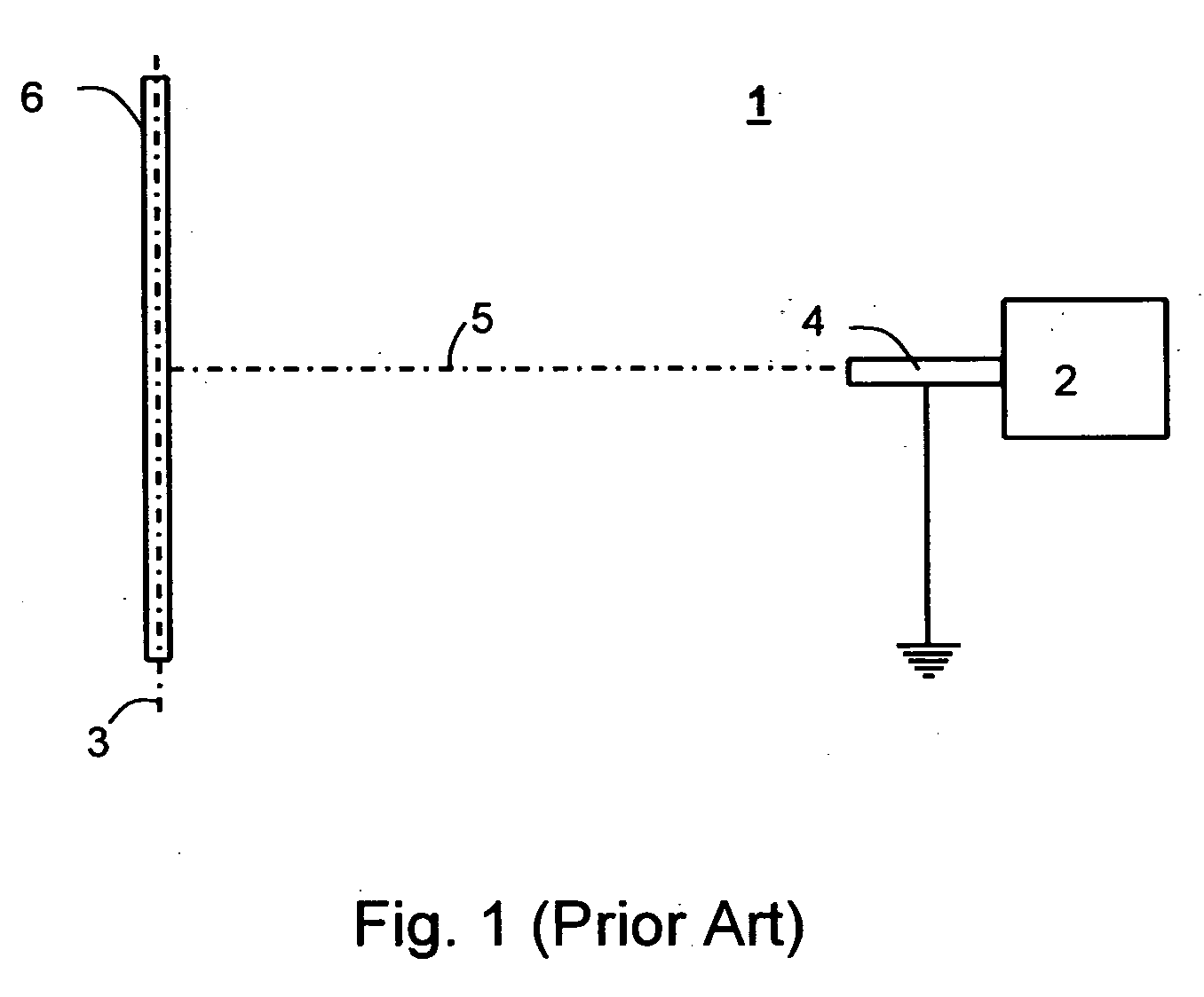
[0314] Reference is now made to FIG. 21, which is an example of non-randomized covering of thin mandrels via conventional electrospinning. A 3-mm cylindrical mandrel was covered by polycarbonate fiber using prior art electrospinning approaches. FIG. 21 is an electron microscope image of the final product, in which axial fiber orientation is well evident. Due to non-uniformities in the electric field, the fibers, while still in motion in the inter-electrode space, are oriented in conformity with the field configuration, and the obtained tubular structure exhibits axial orientation of fibers, and as such is characterized by axial, as opposed to radial strength.

example 2

Random Covering Using Flat Subsidiary Electrode

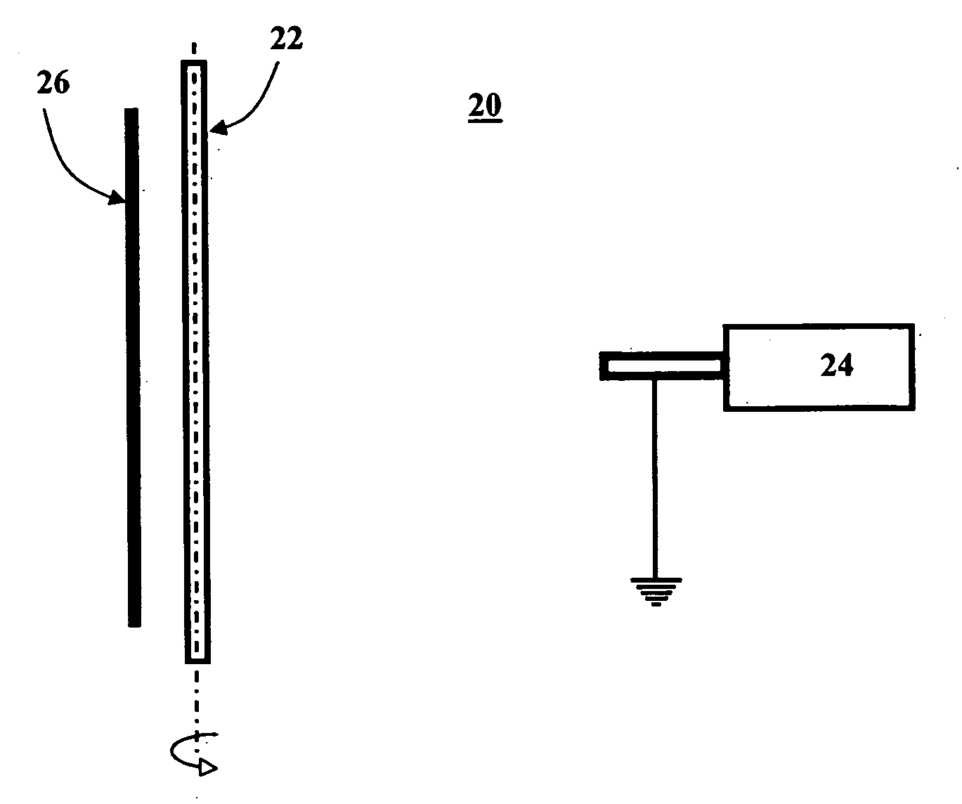
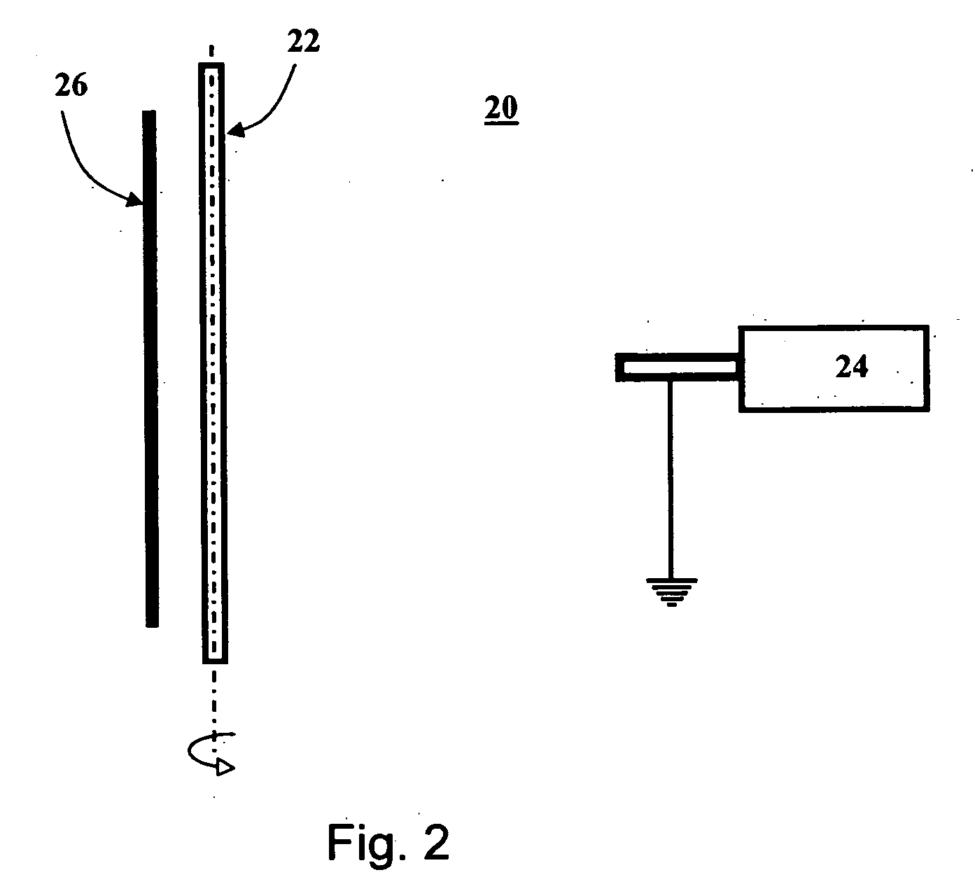
[0315] An apparatus constructed and operative in accordance with the teachings of the present invention incorporating a flat subsidiary electrode positioned 20 millimeters from the mandrel and having the same potential as the mandrel was used to spin a polycarbonate tubular structure of a 3 mm radius. As is evident from FIG. 22, the presence of a subsidiary electrode randomizes fibers orientation.

example 3

Polar-Oriented Covering Using Flat Subsidiary Electrode

[0316] An apparatus constructed and operative in accordance with the teachings of the present invention incorporating a flat, subsidiary electrode positioned 9 millimeters from the mandrel and being at a potential difference of 5 kV from the mandrel was used to spin a polycarbonate tubular structure of a 3 mm radius.

[0317] As illustrated by FIG. 23, reduction of equalizing electrode-mandrel distance results in polar-oriented covering. Thus, by keeping subsidiary electrode and mandrel within a relatively small distance, while providing a non-zero, potential difference therebetween, leads to slow or no fiber charge dissipation and, as a result, the inter-electrode space becomes populated with fiber which are held statically in a stretched position, oriented perpendicular to mandrel symmetry axis. Once stretched, the fibers are gradually coiled around the rotating mandrel, generating a polar-oriented structure.


PUM

PropertyMeasurementUnit
diameteraaaaaaaaaa
angleaaaaaaaaaa
angleaaaaaaaaaa

Abstract

A method of coating a non-rotary object with an electrospun coat, the method comprising, dispensing a charged liquefied polymer through at least one dispensing element within an electric field to thereby form a jet of polymer fibers, and moving the dispensing element relative to the object so as to coat the object with the electrospun coat.

Description

[0001] This application is a continuation-in-part of PCT Patent Application No. PCT / IL2004 / 000917, filed on Oct. 5, 2004, which claims the benefit of U.S. Provisional Patent Application Ser. No. 60 / 508,301, filed on Oct. 6, 2003. [0002] This application is also a continuation-in-part of pending U.S. patent application Ser. No. 10 / 433,621, filed on Jun. 18, 2003, which is a National Phase of PCT Patent Application No. PCT / IL01 / 01168, filed on Dec. 17, 2001, which is a continuation of U.S. patent application Ser. No. 09 / 982,017, filed on Oct. 19, 2001, now abandoned, which claims the benefit of U.S. Provisional Patent Application No. 60 / 276,956, filed on Mar. 20, 2001, and U.S. Provisional Patent Application Ser. No. 60 / 256,323, filed on Dec. 19, 2000. [0003] This application is also a continuation-in-part of pending U.S. patent application Ser. No. 10 / 433,620, filed on Jun. 18, 2003, which is a National Phase of PCT Patent Application No. PCT / IL01 / 01171, filed on Dec. 17, 2001, which...

Claims


Application Information

Patent Timeline
Patent Type & Authority Applications(United States)
IPC IPC(8): B05D1/04B05B5/025H05C1/00
CPCB05B5/08B05D1/007D01D5/0084D01D5/0069B05D1/04D01D5/18
Inventor DUBSON, ALEXANDERKATZ-OZ, ORIBAR, ELI
Owner NICAST LTD
Why Eureka
Try Eureka