

Air based emergency monitor, multimode communication, control and position finder system
- Summary
- Abstract
- Description
- Claims
- Application Information
AI Technical Summary
Benefits of technology
Problems solved by technology
Method used
Image

Examples
Embodiment Construction
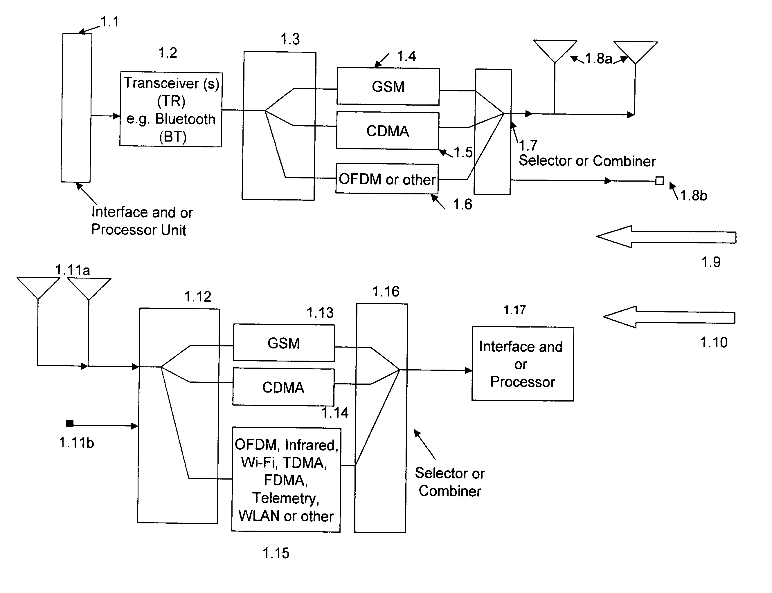
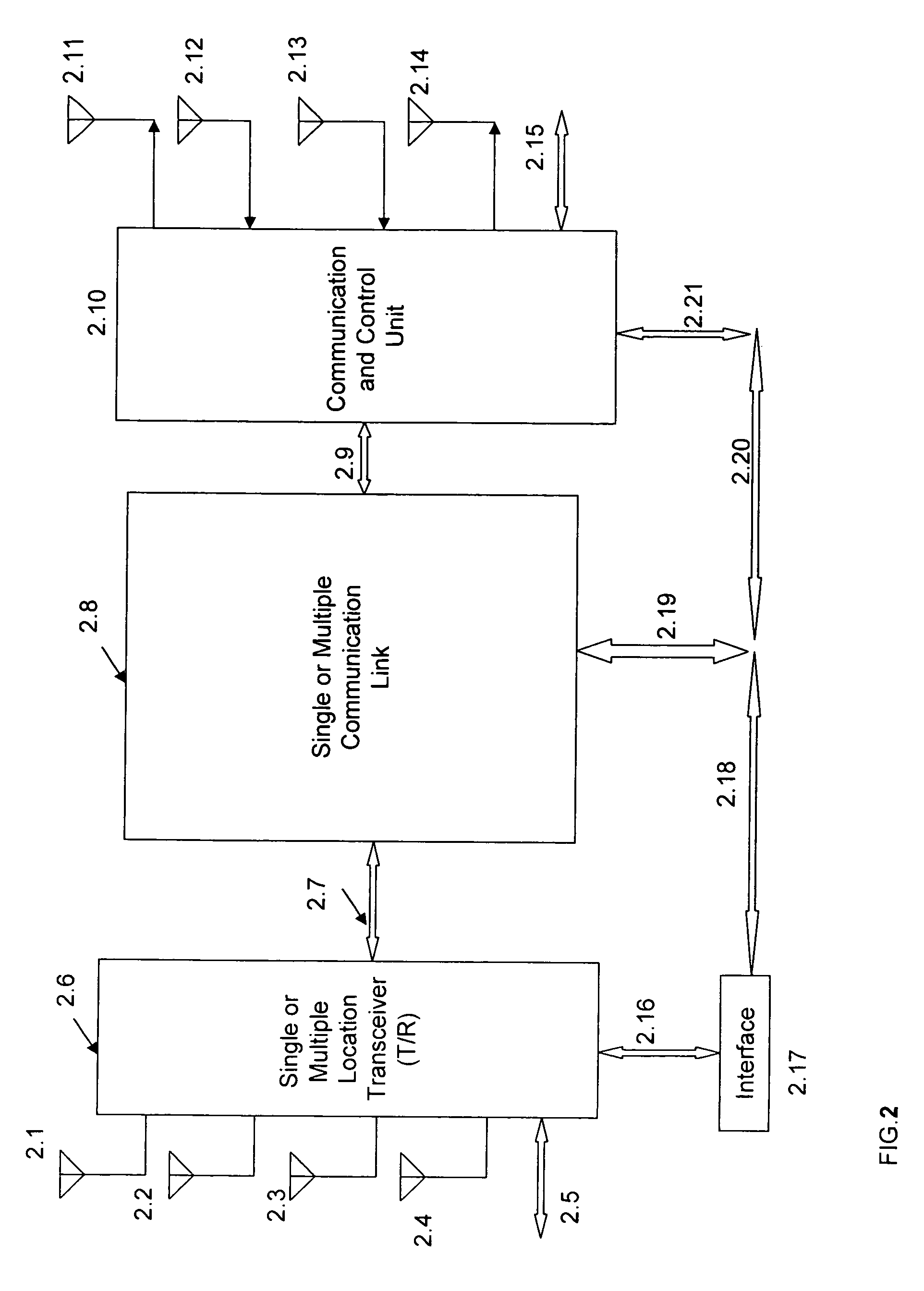
[0233] In this section, the present invention is more fully described with reference to the accompanying drawings in which preferred embodiments of the invention are shown. This invention may, however, be embodied in many different forms and should not be construed as limited to the illustrated embodiments set forth herein. Rather, these embodiments are provided so that this disclosure will be thorough and complete, and will fully convey the scope of the invention to those skilled in the art.
[0234] One or more devices (alternatively designated as units, elements, systems, terminals, devices, leads or connections) are optional in the embodiments. The elements may be interconnected and or used in various configurations. In the figures and relevant descriptions of the figures, as well as in the specifications of this disclosure, some of the units or elements are optional and are not required for certain applications, embodiments and or structures. In this document the term “signal” ha...
PUM
 Abstract
Description
Claims
Application Information