Method for manufacturing fired product having luminous function, fired product manufactured thereby, and evacuation route guiding sign device using fired product

a technology of luminous function and manufacturing method, which is applied in the direction of luminescent compositions, chemistry apparatus and processes, metal layered products, etc., can solve the problems of low afterglow function, increase of cost, and limitations of improvement of afterglow capability, so as to reduce the afterglow function and prevent the occurrence of crazing and peeling, the effect of reducing the size of the firing process

Inactive Publication Date: 2007-02-15
UNIVERSAL LIGHT
View PDF0 Cites 12 Cited by
  • Summary
  • Abstract
  • Description
  • Claims
  • Application Information

AI Technical Summary

Benefits of technology

[0051] According to first aspect of the present invention, the occurrence of crazing and peeling caused by using luminous material particles having a large particle size in the firing process can be prevented, and also a decrease of the afterglow function can be inhibited to a minimum by reducing oxidation degradation of the luminous material particles. Thus, the afterglow function can be enhanced by using the luminous material particles having a large particle size. Additionally, the afterglow luminance can be enhanced even if the luminous material particles is a single layer, but a plurality of layers of the luminous material particles is stacked in the present invention to further enhance the afterglow luminance. This is considered that the luminous material particles are not spherical but are irregular in shape, so that sunlight and artificial light can pass through the gaps formed between luminous material particles.
[0052] According to the second aspect of the present invention, the luminous material particles can be immobilized on a metal plate of which the coefficient of thermal expansion is largely different from that of a ceramic material, so that the excellent capabilities, which the ceramic material does not have, of the metal plate can be utilized, in addition to the above-mentioned effects.
[0053] According to the third aspect of the present invention, the afterglow capabilities such as afterglow luminance and afterglow time can be improved compared with known evacuation route guiding sign members made of fired products.
[0054] According to any of fourth to tenth aspect of the present invention, the guiding sign device using the luminous material can be retrofitted to a floor or wall. The effects are as follows:
[0055] 3. Since the fore of the mounting plate (the direction of the arrow on the guiding sign-board) is in a chevron shape, the direction indicated by the arrow can be highlighted to be readily recognized. Thus, the functionality is improved, and the design is good. Additionally, by providing the mounting plate with two chevron-shaped sides opposing each other, the guiding sign-board can be adhered to the mounting plate without any attention to which is the front side.
[0056] According to any of eleventh to seventh aspect of the present invention, the evacuation route guiding sign device using the luminous material can achieve the following effects.

Problems solved by technology

However, the afterglow function is low because of the small particle size of the luminous material particles.
The repetition of screen printing and firing for enhancing the afterglow functions requires time and effort, resulting in an increase of cost.
Furthermore, since a particle size of luminous material particles is restricted, an improvement in the afterglow capability has limitations compared with that when luminous material particles having a large particle size are used.
Therefore, even if an amount of the luminous material particles is increased, the afterglow capability cannot be dramatically improved.
Additionally, crazing and peeling tend to occur with an increase in repetition of firing.
However, this decreases a ratio of the luminous material particles; thus, the afterglow capability cannot be improved.
However, luminous material particles having a large particle size cannot be used for the conventional screen printing.
Thus, crazing and peeling tend to occur, and mass production is difficult.
However, this technology is different from a technology that luminous material particles having a large particle size is used for increasing afterglow luminance and afterglow time.
However, this known example does not disclose a solution for peeling and crazing when the luminous paint is applied to a substrate used in firing.
However, although this known example discloses the use of the luminous particles having a large particle size, a solution for peeling or crazing, which occurs when the luminous particles having a large particle size are formed into a sheet, is not disclosed.
However, in the sign device having the rivet, the adhesion between the luminous ceramic and the rivet body is poor.
When the sign device is installed on a floor which is walked on, the rivet body is damaged and the fixation is loosened.
This causes peeling of the luminous ceramics.
However, even if a sign is self-luminous, the sign cannot be clearly seen in the dark and moreover in black smoke.
Therefore, it is a very troublesome task and takes a lot of time and cost.
However, since a resin is used as a material for the sheet, the sheet is melted by the heat of fire.
Furthermore, the sheet has endurance problems.
Namely, wear of the sheet proceeds when the sheet is applied on a passageway
However, in these conventional cases, the signs cannot be readily seen in the dark or in the smoke.
The conventional evacuation route guiding sign devices utilizing a luminous material are useless for the visually impaired.
Therefore, such devices are insufficient as a safety measure.
However, since a resin is used as a raw material in this known example, the device may be melted by the heat of fire.
Therefore, it may be useless for fire evacuation.
When the device is installed on a floor, a difference in level on the floor is large.
Furthermore, the device cannot be readily installed in a tile or concrete floor.
In particular, the device cannot be retrofitted to subway platforms, steps, and passageways.

Method used


Image

  • Method for manufacturing fired product having luminous function, fired product manufactured thereby, and evacuation route guiding sign device using fired product
  • Method for manufacturing fired product having luminous function, fired product manufactured thereby, and evacuation route guiding sign device using fired product
  • Method for manufacturing fired product having luminous function, fired product manufactured thereby, and evacuation route guiding sign device using fired product

Examples


example 1

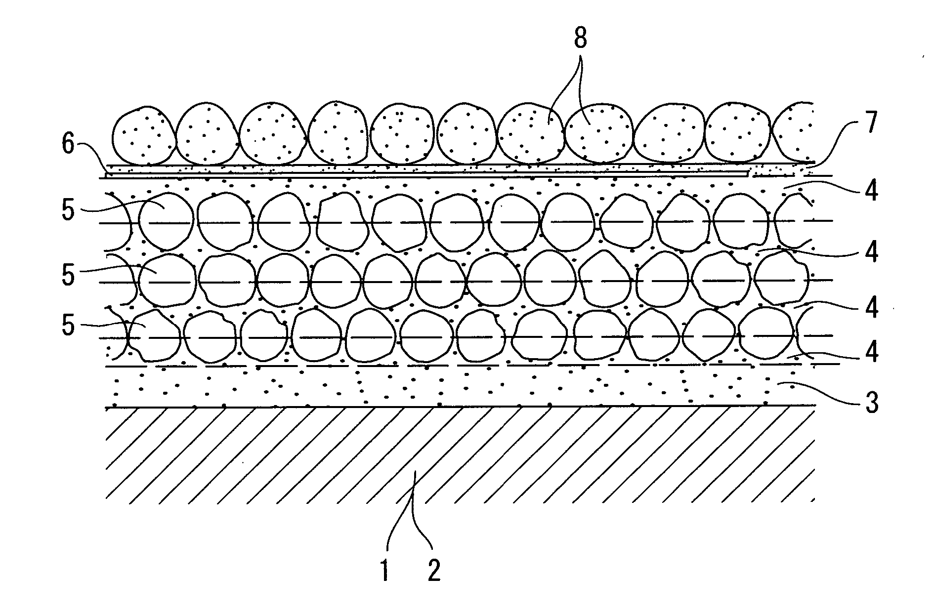
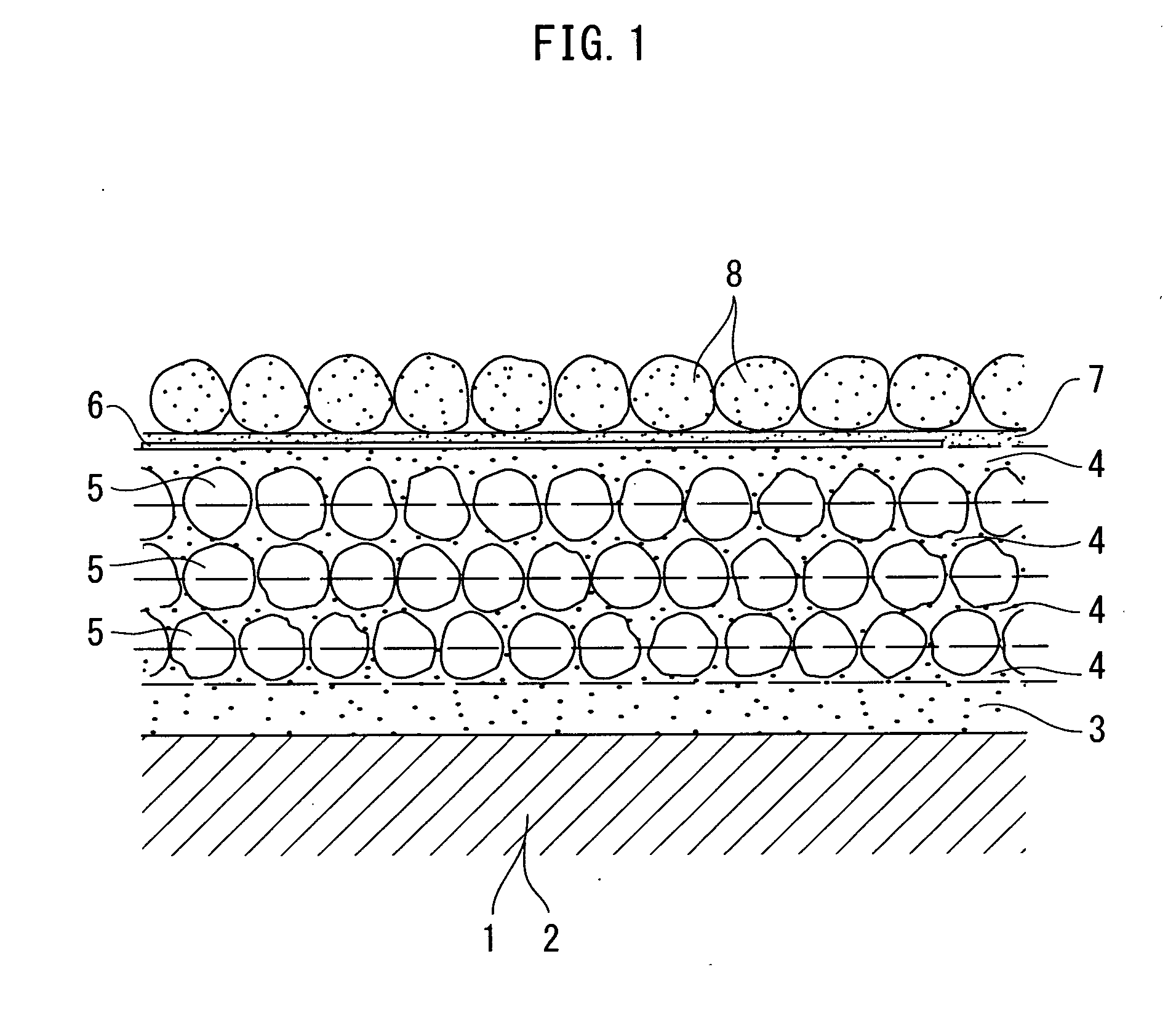
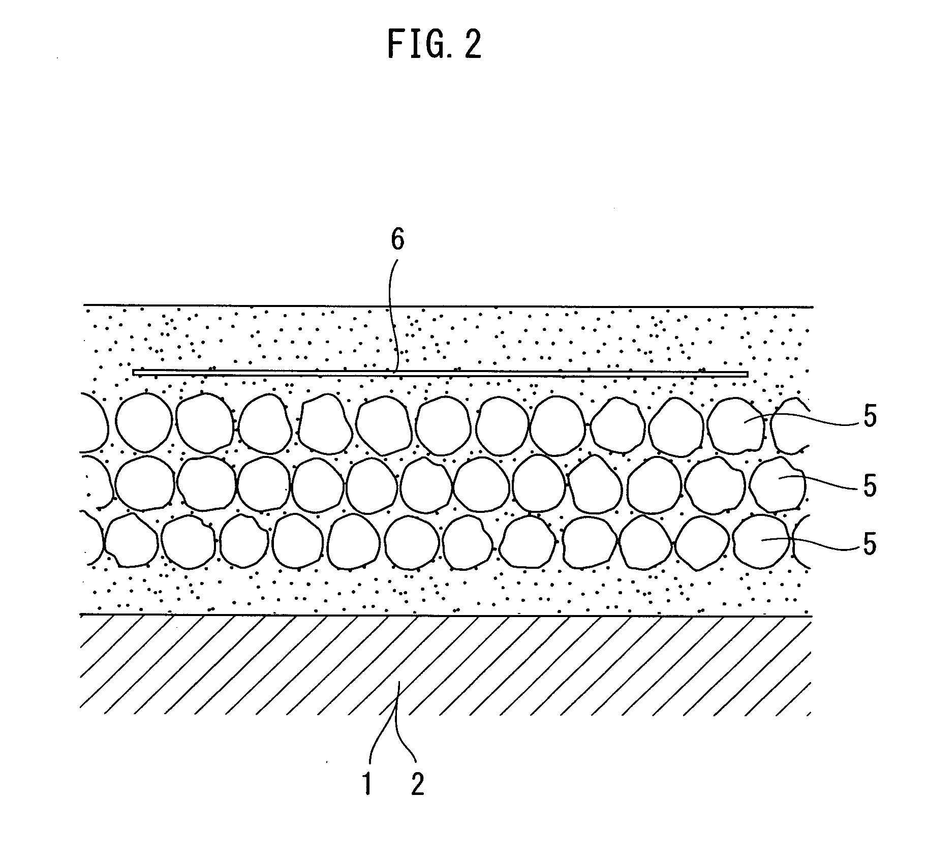
[0082] With reference to FIGS. 1 to 4, material-adapting glass frit 3 is adhered on a surface of a plate-shaped ceramic material 1 or a metal plate 2 by screen printing or spray coating. The material-adapting glass frit 3 is adhered so as to cover the whole surface of the ceramic material 1 or the metal plate 2 with a uniform thickness of, for example, 100 to 200 μm, preferably, 150 μm. The difference in coefficient of thermal expansion between the ceramic material 1 and luminous material particles 5 or between the metal plate 2 and the luminous material particles 5 can be alleviated by increasing the thickness of the material-adapting glass frit 3.

[0083] Examples of the materials for the ceramic material 1 include glass, tiles, and ceramics. Examples of the materials for the metal plate 2 include iron, stainless steel, and copper. The ceramic material 1 is less affected by expansion caused by firing than the metal plate 2, and is corrosion-free. On the other hand, the metal plate ...

example 2

[0121] With reference to FIGS. 5 to 11, Example 2 according to the present invention will now be described in detail.

[0122]FIG. 5 shows a state in which an evacuation route guiding sign device according to the present invention is retrofitted on a floor 301 so as to indicate the direction to an emergency exit 300. FIG. 6 is a plan view showing the entire evacuation route guiding sign device. FIG. 7 is an enlarged cross-section view taken along the line B-B′ of FIG. 6. FIG. 8 is a plan view of a mounting plate. FIG. 9 is a cross-section view taken along the line C-C′ of FIG. 8. FIG. 10 is a plan view of a mounting plate provided with Braille. FIG. 11 is an explanatory drawing of a mounting plate having a rough bottom face.

[0123] In the drawings, reference numeral 100 denotes a mounting plate for the evacuation route guiding sign device. The mounting plate 100 is a flat rectangle with a short side having a chevron 104. As shown in FIG. 10, the chevron 104 may be formed at both sides...

example 3

[0131] With reference to FIGS. 12 to 17, an example of an evacuation route guiding sign device (referred to as sign device hereinafter) according to the present invention will be described in detail.

[0132]FIG. 12 is an explanatory drawing of a state in which sign devices 200 are fixed on a floor 301 at a certain interval toward an emergency exit 300. FIG. 13 is an exploded perspective view of the sign device 200. FIG. 14 is an enlarged cross-section view taken along the line B-B′ of FIG. 12.

[0133] In FIGS. 12 to 14, a display plate 201 of the sign device 200 has a luminous paint (pigment) layer 203 formed by firing on a surface of a quadrangular stainless steel plate 202, a sign of an arrow 204 for indicating an evacuation route on the surface, and a first frame 205 having a certain width and surrounding the luminous paint layer 203. The first frame 205 has six bolt-holes 206.

[0134] A mounting plate 207 is formed by press working of a stainless steel plate. The mounting plate 207...


PUM

PropertyMeasurementUnit
particle sizeaaaaaaaaaa
thicknessaaaaaaaaaa

Abstract

A fired product having a luminous function is manufactured by: adhering material-adapting glass frit to a surface of a ceramic material; adhering coating glass frit to the surface of the material-adapting glass frit after drying of the material-adapting glass frit; adhering luminous material particles having a particle size of 50 to 250 μm in one uniform layer to the coating glass frit layer before drying of the coating glass frit so that the upper portions of the luminous material particles are partly exposed from the coating glass frit; alternately stacking coating glass frit and luminous material particles several times; covering the topmost luminous material particles partly exposing from the coating glass frit by adhering coating glass frit; printing an image portion on the surface of the coating glass frit after drying of the coating glass frit; adhering adapting glass frit at a predetermined thickness to the coating glass frit having the printed image portion; uniformly adhering protecting glass frit particles having a large particle size to the surface of the adapting glass frit; and firing the adhered stack at high temperature, wherein the material-adapting glass frit has a coefficient of thermal expansion of an intermediate value between those of the ceramic material and the luminous material particles, the coating glass frit has a coefficient of thermal expansion substantially the same as that of the luminous material particles, and the adapting glass frit has a coefficient of thermal expansion of an intermediate value between those of the luminous material particles and the protecting glass frit particles having a large particle size. This fired product is used in an image forming part of an evacuation route guiding sign device as a fired product layer.

Description

BACKGROUND OF THE INVENTION [0001] 1. Field of the Invention [0002] The present invention relates to methods for manufacturing fired products having luminous functions with good afterglow luminance and long afterglow time, and relates to fired products having the luminous functions. Furthermore, the present invention relates to evacuation route guiding sign devices using the fired products. [0003] 2. Description of the Related Art [0004] In the ceramics industry, screen printing is broadly used for painting surfaces of fired products because of its easiness. With such an easy screen printing, mixtures of luminous material particles and glass frits are printed on surfaces of ceramic raw materials, and then the ceramic raw materials are fired at high temperature to obtain fired products having luminous functions. The fired products having luminous functions are used as, for example, evacuation route guiding sign members in subway premises. [0005] Recent studies have revealed that afte...

Claims


Application Information

Patent Timeline
Patent Type & Authority Applications(United States)
IPC IPC(8): C09K11/08C09K11/77B32B17/06B32B9/00
CPCC09K11/7792
Inventor TANAKA, HIROSHIFUKUDA, TOMOKAZUMATSUMOTO, GOUNAKAGAWA, KOICHIRO
Owner UNIVERSAL LIGHT
Why Eureka
Try Eureka