
Chemically amplified positive resist composition and patterning process

a positive resist and composition technology, applied in the field of chemically amplified positive resist compositions, can solve the problem that the electron beam imagewise writing process takes a longer time than the conventional block exposure process, and achieve the effects of high sensitivity, high contrast and high resolution

Active Publication Date: 2007-02-15
SHIN ETSU CHEM CO LTD
View PDF6 Cites 12 Cited by
  • Summary
  • Abstract
  • Description
  • Claims
  • Application Information

AI Technical Summary

Benefits of technology

The composition achieves high sensitivity, high resolution, and excellent age stability, forming a satisfactory pattern profile independent of the substrate, making it suitable for industrial micropatterning applications, particularly in electron beam lithography.

Problems solved by technology

However, electron beam imagewise writing takes a longer time than the conventional block exposure process.

Method used


Image

  • Chemically amplified positive resist composition and patterning process
  • Chemically amplified positive resist composition and patterning process
  • Chemically amplified positive resist composition and patterning process

Examples


synthesis example 1

Synthesis of 2,4,6-triisopropylbenzenesulfonic acid

[0091] To 30.2 g (0.1 mol) of commercially available 2,4,6-triisopropylbenzenesulfonyl chloride were added 30 g of dimethyl sulfoxide and 30 g of water. The mixture was heated and stirred on an oil bath at 80° C. for 3 hours. The dimethyl sulfoxide / water solution was ready for use in the subsequent step of anion exchange reaction.

synthesis example 2

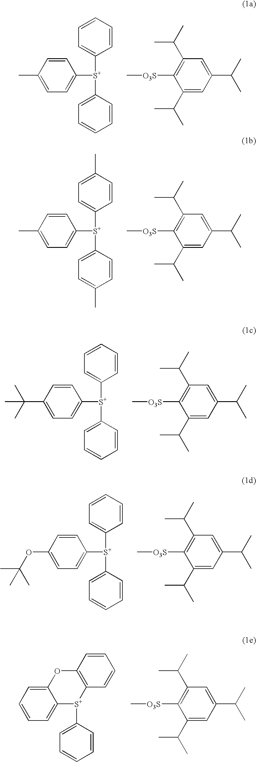
Synthesis of diphenyl-4-methylphenylsulfonium 2,4,6-triisopropylbenzenesulfonate

[0092] In 100 g of dichloromethane were dissolved 20.2 g (0.1 mol) of diphenyl sulfoxide and 32.6 g (0.3 mol) of trimethylsilyl chloride. To the reaction solution which was ice cooled, a tetrahydrofuran solution of 4-methylphenylmagnesium chloride (0.3 mol) which was separately prepared was added dropwise such that the temperature might not exceed 20° C. Then, 10 g of 35 wt % aqueous hydrochloric acid and 200 g of water were added such that the temperature might not exceed 20° C. Finally 100 g of diethyl ether was added.

[0093] The water layer was separated, to which the dimethyl sulfoxide / water solution of 2,4,6-triisopropylbenzenesulfonic acid prepared in Synthesis Example 1 and 300 g of dichloromethane were added, followed by stirring.

[0094] The organic layer was separated, and washed with 200 g of water three times. The organic layer was the concentrated. Diethyl ether was added to the concentrate ...

synthesis example 3

Synthesis of tris(4-methylphenyl)sulfonium 2,4,6-triisopropylbenzenesulfonate

[0096] Using a tetrahydrofuran solution of 4-methylphenylmagnesium chloride, thionyl chloride, and trimethylsilyl chloride, tris(4-methylphenyl)sulfonium chloride was synthesized according to the formulation shown in JP-A 8-311018. This sulfonium chloride was mixed with the sulfonic acid of Synthesis Example 1 whereupon anion exchange reaction was carried out as in Synthesis Example 2, yielding the target compound. The target compound was obtained as white crystals in an amount of 22.4 g and a yield of 38%. It was analyzed by 1H-NMR and IR spectroscopy, with the data shown below.

[0097]1H-NMR (CDCl3, σppm) 1.17-1.19 (12H, d, Ha′), 1.20-1.22 (6H, d, Ha), 2.40 (9H, s, He), 2.77-2.90 (1H, m, Hb), 4.70-4.82 (2H, m, Hc), 7.01 (2H, s, Hd), 7.36-7.39 (6H, d, Hg), 7.66-7.71 (6H, d, Hf) IR (cm−1) 3045, 2960, 2863, 1591, 1490, 1457, 1421, 1403, 1199, 1162, 1083, 1070, 1049, 1012, 809, 674, 588, 507


PUM

PropertyMeasurementUnit
feature sizeaaaaaaaaaa
temperatureaaaaaaaaaa

Abstract

A chemically amplified positive resist composition comprising a specific 2,4,6-triisopropylbenzenesulfonate compound as a photoacid generator, a polymer which changes its solubility in an alkaline developer under the action of acid, and a basic compound has a high sensitivity, a high contrast of dissolution of resist film, a high resolution, and good storage stability.

Description

CROSS-REFERENCE TO RELATED APPLICATION [0001] This application is a Continuation of co-pending Application Ser. No. 11 / 105,457, filed on Apr. 14, 2005, the entire contents of which are hereby incorporated by reference and for which priority is claimed under 35 U.S.C. § 120. [0002] This application also claims priority to Patent Application No. 2004-120635 filed in Japan on Apr. 15, 2004, the entire contents of which are hereby incorporated by reference and for which priority is claimed under 35 U.S.C. § 119.TECHNICAL FIELD [0003] This invention relates to chemically amplified positive resist compositions which are sensitive to high-energy radiation such as UV, deep UV, electron beams, x-rays, excimer laser beams, γ-rays, and synchrotron radiation and suitable as micropatterning materials for the fabrication of VLSI and photomasks, and a patterning process using the same. BACKGROUND ART [0004] In the drive for higher integration in integrated circuitry, it is desired to form patterns...

Claims


Application Information

Patent Timeline
Patent Type & Authority Applications(United States)
IPC IPC(8): G03C1/00C08F212/14G03F7/004C08F220/10G03C1/492G03F7/039H01L21/027
CPCG03F7/0045G03F7/0392G03F7/0397Y10S430/123Y10S430/108Y10S430/111Y10S430/106G07F13/10G07F17/0092
Inventor KOITABASHI, RYUJIWATANABE, SATOSHIOHSAWA, YOUICHI
Owner SHIN ETSU CHEM CO LTD
Learn More