Sensor head, gas sensor and sensor unit

a sensor unit and sensor head technology, applied in the field of sensor head, can solve the problems of weak expansion resistance, low reaction speed, thick sensitive film b, etc., and achieve the effect of facilitating the achievement of a strong expansion resistance and high response tim

Inactive Publication Date: 2007-02-22
TOPPAN PRINTING CO LTD +1
View PDF4 Cites 10 Cited by
  • Summary
  • Abstract
  • Description
  • Claims
  • Application Information

AI Technical Summary

Benefits of technology

[0028] As with the sensor unit as according to the third aspect, the sensor unit according to the fourth aspect of the present invention facilitates an achievement of a drastically improved sensor unit providing simultaneously a higher sensitivity and a higher response time than those of the flat plane surface acoustic wave device of the earlier technology. Moreover, a thin sensitive film facilitates an achievement of a strong structure against expansion and contraction of the film due to variation in external temperature and / or variation in reaction heat temperature of the film itself, and repetitive changes in physical crystal structure due to chemical reaction or occlusion of atoms. In particular, integration of the high frequency generator and the detection / output unit onto the three-dimensional base body facilitates an achievement of a light and compact sensor unit.

Problems solved by technology

Accordingly, there is a disadvantage that the sensitive film 15 as a specific gas occluding thin film makes the reaction speed lower.
In addition, there is a disadvantage that the thick sensitive film 15 is weak to phase transition caused by reaction of the thin film, which is ascribable to adsorption or occlusion of specific gas molecules, is weak to physical changes such as volume expansion or contraction due to change in temperature, and is weak to impacts caused by repetition of the physical changes.
However, it is difficult for surface acoustic waves on the flat plane to completely avoid influence of dispersion, resulting in distortion of the waveform.
In addition, suppressing leakage from a region of the waveguide having a large curvature formed on the flat plane is impossible, resulting in attenuation of the surface acoustic waves.

Method used


Image

  • Sensor head, gas sensor and sensor unit
  • Sensor head, gas sensor and sensor unit
  • Sensor head, gas sensor and sensor unit

Examples


first embodiment

(FIRST EMBODIMENT)

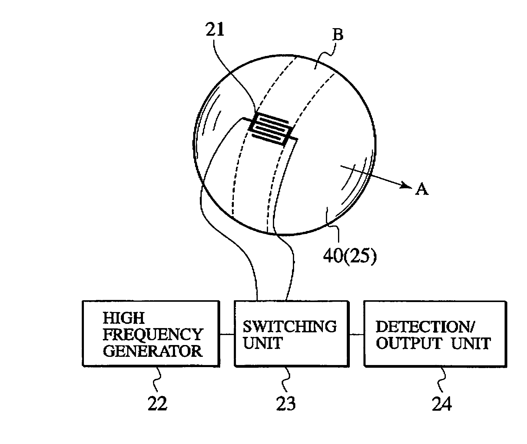
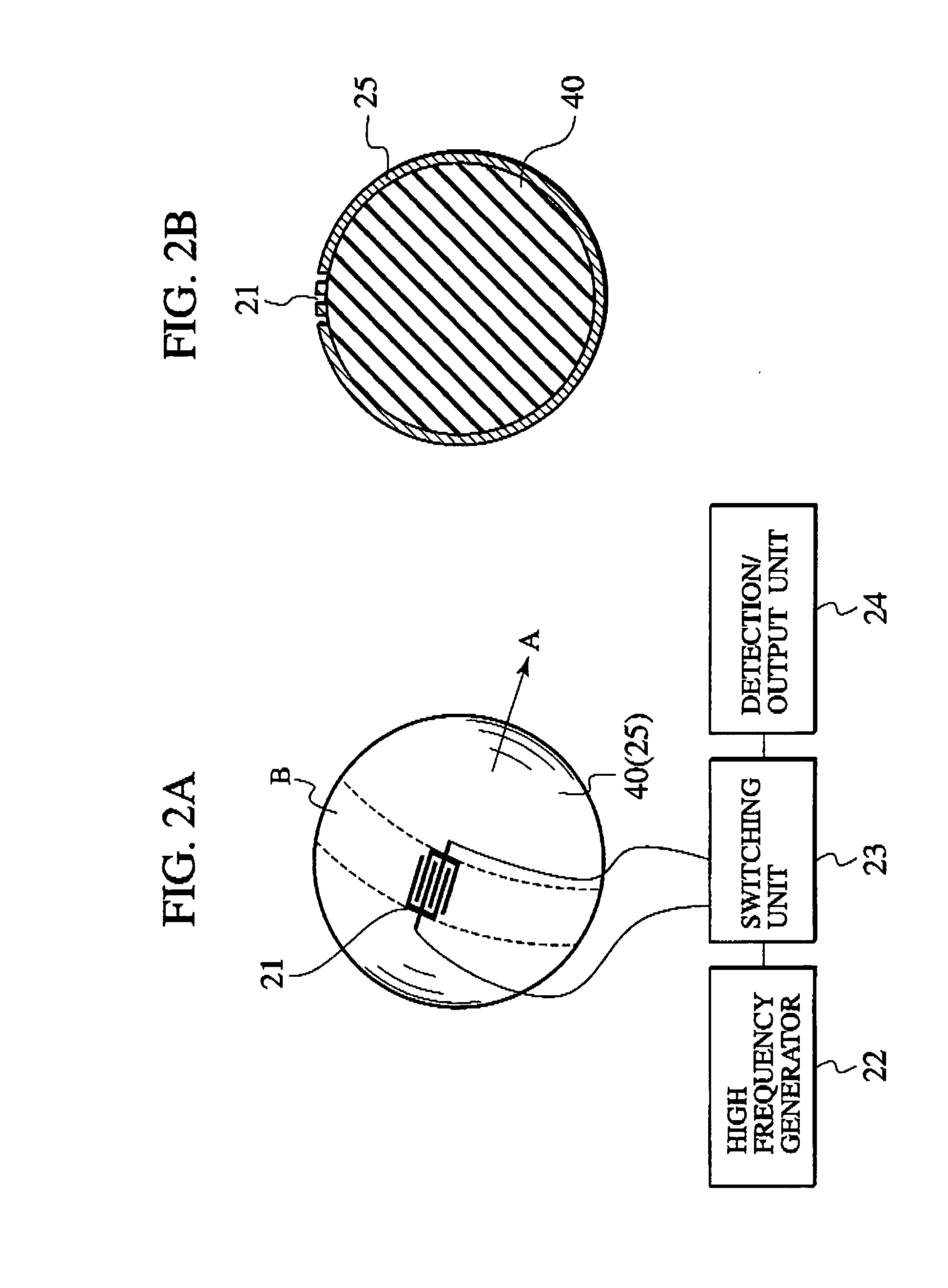
[0053] As shown in FIGS. 2A and 2B, a sensor head according to a first embodiment of the present invention encompasses a three-dimensional base body 40, which has a curved surface allowing definition of a circular orbital band B, an electroacoustic transducer 21, which is deployed on the orbital band B of the three-dimensional base body 40 and excites surface acoustic wave so as to perform multiple roundtrips along the orbital band B, and a sensitive film 25, which is formed on almost the entire surface of the orbital band B of the three-dimensional base body 40 and is configured to be reacted with specific gas molecules.

[0054] A homogeneous material sphere 40 made of piezoelectric crystal is used as the three-dimensional base body 40. A sphere of single crystal such as quartz, lithium niobate (LiNbO3), lithium tantalate (LiTaO3), piezoelectric ceramics (PZT), or bismuth germanium oxide (Bi12GeO20) may be used as the homogeneous material sphere 40. The sensitive f...

second embodiment

(SECOND EMBODIMENT)

[0065] As shown in FIG. 4A, a sensor head according to a second embodiment of the present invention encompasses a three-dimensional base body 40, which has a curved surface allowing definition of a circular orbital band B, an electroacoustic transducer 21, which is deployed on the orbital band B of the three-dimensional base body 40 and excites surface acoustic wave so as to perform multiple roundtrips along the orbital band B, and a sensitive film 25, which is formed on a part of the surface of the orbital band B of the three-dimensional base body 40 and configured to react with specific gas molecules. The three-dimensional base body 40 is a homogeneous material sphere 40 as with the first embodiment, but is different from the first embodiment in that a sensitive film 26 is formed only on a part of the homogeneous material sphere 40. An interdigital transducer 21, which serves as an electroacoustic transducer 21, is formed on a part of the equator of the homogene...

third embodiment

(THIRD EMBODIMENT)

[0072] As shown in FIGS. 6A and 6B, a sensor head according to a third embodiment of the present invention includes a thin piezoelectric film 41 formed on at least a part of the surface of a homogeneous material sphere 40 made of a material having homogeneous elastic characteristics. It is different from the first and second embodiments in that the homogeneous material sphere 40 may be made of a material without piezoelectricity (non-piezoelectric material) since the thin piezoelectric film 41 is formed on the surface of the homogeneous material sphere 40. Therefore, the homogeneous material sphere 40 may be made of an amorphous material such as borosilicate glass, and a glass material such as quartz glass. The thin piezoelectric film 41 may be made of cadmium sulfide (CdS), zinc oxide (ZnO), zinc sulfide (ZnS), or aluminum nitride (AlN), and may he deposited on the surface of the homogeneous material sphere 40 through well-known sputtering or vacuum evaporation.

[...


PUM

PropertyMeasurementUnit
thicknessaaaaaaaaaa
sizeaaaaaaaaaa
sizeaaaaaaaaaa

Abstract

The present invention includes a three-dimensional base body (40) having a curved surface allowing definition of a circular orbital band (B), an electroacoustic transducer (21) arranged on the orbital band (B) of the three-dimensional base body (40) and configured to excite surface acoustic wave to perform multiple roundtrips along the orbital band (B), and a sensitive film (25) formed on at least a part of the orbital band (B) of the three-dimensional base body (40) and configured to react with a specific gas molecule. The surface acoustic wave experienced the multiple roundtrips along the orbital band (B) is then converted into a high frequency electric signal again by an interdigital transducer (21). The resulting high frequency electric signal is transferred to a detection/output unit (24) via a switching unit (23) and then detected by the detection/output unit (24).

Description

TECHNICAL FIELD [0001] The present invention relates to a sensor head. In particular, it relates to a sensor head using a surface acoustic wave device, a gas sensor using the surface acoustic wave device, and a sensor unit assembled with the sensor head. BACKGROUND ART [0002] A variety of gas sensors such as catalytic combustion sensor, a semiconductor sensor, or a surface acoustic wave sensor have been used. Of these sensors, the surface acoustic wave sensor uses a flat-plane type surface acoustic wave device as shown in FIG. 1. As shown in FIG. 1, a transmitter-side interdigital transducer 11 for exciting surface acoustic waves, a receiver-side interdigital transducer 13 serving as a piezoelectric transducer to convert the surface acoustic waves into a high frequency electric signal again, the electric signal will then be detected by an output unit 14, and a sensitive film 15 serving as a propagating path of the surface acoustic wave from the transmitter-side interdigital transduc...

Claims


Application Information

Patent Timeline
Patent Type & Authority Applications(United States)
IPC IPC(8): G01N31/22G01N29/02G01N29/46
CPCG01N29/022G01N29/2462G01N29/46G01N2291/0215G01N2291/0217G01N2291/0256G01N2291/02818G01N2291/02881G01N2291/0423
Inventor YAMANAKA, KAZUSHINAKASO, NORITAKATAKEDA, NOBUO
Owner TOPPAN PRINTING CO LTD
Why Eureka
Try Eureka