
Optimized heat roll apparatus

a heat roll and apparatus technology, applied in the field of heat roll, can solve the problems of limiting the lateral heat conduction rate to a lower rate, inefficient external fluid heating systems that accompany conventional heated calendering rolls, and high cost of cross-bore fluid channels and rotating seals. achieve the effect of reliabl

Inactive Publication Date: 2007-02-22
COMAINTEL
View PDF5 Cites 4 Cited by
  • Summary
  • Abstract
  • Description
  • Claims
  • Application Information

AI Technical Summary

Benefits of technology

[0032] The optimized heated roll apparatus of the present invention is generally designed to enable faster, more controllable heating, to a higher temperature, with lower energy expenditure, and cooled more quickly with a simpler cooling system, than conventional rolls that are predominantly manufactured from ferrous alloys. The preferred embodiments of the present invention therefore each provide some combination of the following core advantages;
[0033] Lower thermal mass (mass×specific heat) than conventional heated ferrous rolls, enabling faster heating by external induction and faster cooling by any suitable means.
[0034] More conductive interior material properties than conventional heated ferrous rolls, enabling higher lateral heat conduction to reduce lateral temperature variations.

Problems solved by technology

While this may be due to strength considerations, it is often due to a lack of appreciation of the how this depth affects the process response time, energy consumption, and required heating system size.
Or, conversely, the relatively low thermal conductivity of ferrous metals may limit the lateral heat conduction to a rate lower than is optimal for a specific application.
The historical use of internal heating fluids, and the need for high roll stiffness during calendering has resulted in conventional heated calendering rolls being relatively thick-walled (typically with wall thickness of more than one inch, or solid throughout), with elaborate and expensive cross-bored fluid channels and rotating seals.
Furthermore, conventional heated calendering rolls are made of an essentially homogeneous, moderately thermally-conductive material, such as steel, throughout their full wall thickness, to permit unimpeded heat conduction from the inside to the outside.
The external fluid heating systems that accompany conventional heated calendering rolls are also relatively inefficient due to piping circuit heat losses and energy conversions losses (their original source of energy is often natural gas or heating oil, requiring energy conversion with attendant combustion and heat exchanger inefficiencies).
Requisite external fluid temperature control systems must also be able to cool the fluid (to enable precise roll temperature control, and to remove the heat quickly during stoppages), which adds to the overall complexity and cost.
A primary limitation of conventional heated calendering rolls is that they are relatively thermally-conductive throughout their substantial depth, requiring that their whole mass be heated up to attain a desired outer surface temperature.
Furthermore, the large mass of internal fluid used by conventional heated calendering rolls also has to be heated before it can heat the roll, or cooled before it can cool the roll.
The large roll and fluid mass, and the long radial conductive path throughout the depth of the roll, thus produces a large thermal inertia that reduces the response time of roll temperature controls to process disturbances on continuous operations, and which furthermore thus imposes a severe setup and change-over delay on discontinuous, batch-type calendering processes.
Over-sizing these fluid-cooling and heating systems beyond what steady-state conditions require adds significantly to their size, complexity and initial cost, and further aggravates their inherent energy inefficiencies.
A further limitation of conventional heated calendering rolls is that they are homogenous across their width, and the internal fluid paths are continuous across their entire width, making it impossible to locally heat just one cross-direction region of the roll.
If the roll temperature is not sufficiently uniform it may impart a non-uniform temperature profile to the web(s) before or during laminating or embossing.
This in turn may affect the web's localized compressibility, malleability, and dimensional stability, leading to variable finished product quality.
While on high throughput web manufacturing operations such as papermaking it is cost effective to measure and control web properties in narrow zones across the width, such investments are usually not viable on converting applications that are typically much narrower and slower.
Consequently, narrow zone control of effective roll heating means such as external magnetic induction, is often not commercially viable on converting applications.
Unfortunately, such rolls are relatively expensive to build, they often require fluid connections, and they typically require a significant internal structural mass, which along with the internal fluid itself, adds to their thermal inertia to lengthen their heat-up response.
The response time and cross-direction heat migration limitations mentioned above for web calendering applications apply equally to web converting applications, especially in that preheating cans are homogenous across their width, with a single internal steam chamber, making it difficult to locally heat just one lateral region of the preheater can to localize the drying or heating effect in a given lateral region of the web.
As with the previously described heated calendering applications, the historical use of internal fluids has resulted in conventional curing / heat-setting rolls being relatively heavy-walled with elaborate and costly internal fluid channels and rotating seals.
These curing / heat-setting rolls are also made of a homogeneous, thermally-conductive material, such as steel, throughout their depth, and are also typically accompanied by an expensive and over-sized external fluid cooling and heating system to quickly remove and add heat before and after stoppages.
Curing / heat-setting rolls are also homogenous across their width, and the internal fluid paths are continuous across their entire width, making it impossible to locally heat just one cross-direction region of the roll.
Web shrinkage is typically a somewhat non-uniform phenomenon, occurring more freely and uniformly at the edges, and less easily and uniformly near the center of the web due to friction between it and contacting machine elements, such as rolls.
This cross-direction non-uniformity often produces wrinkles in the web as it shrinks, which in turn may have a deleterious effect on the final quality of the web.
The above examples clearly illustrate that on many web manufacturing and converting applications the design of conventional heated rolls, and their method of heating, imposes significant limitations, and that these limitations will apply equally or in part to other web applications involving heated rolls.
Unfortunately the above-described conventional rolls cannot fully exploit the benefits of this new induction heating technology.
Even though state-of-the-art induction technology heats just the surface region of a steel roll, where the thermal energy is actually needed by the process, that heat must unfortunately migrate into the roll and internal fluid, and heat up the entire combined mass before the surface temperature can be stabilized at a target value.

Method used


Image

  • Optimized heat roll apparatus
  • Optimized heat roll apparatus
  • Optimized heat roll apparatus

Examples


Embodiment Construction

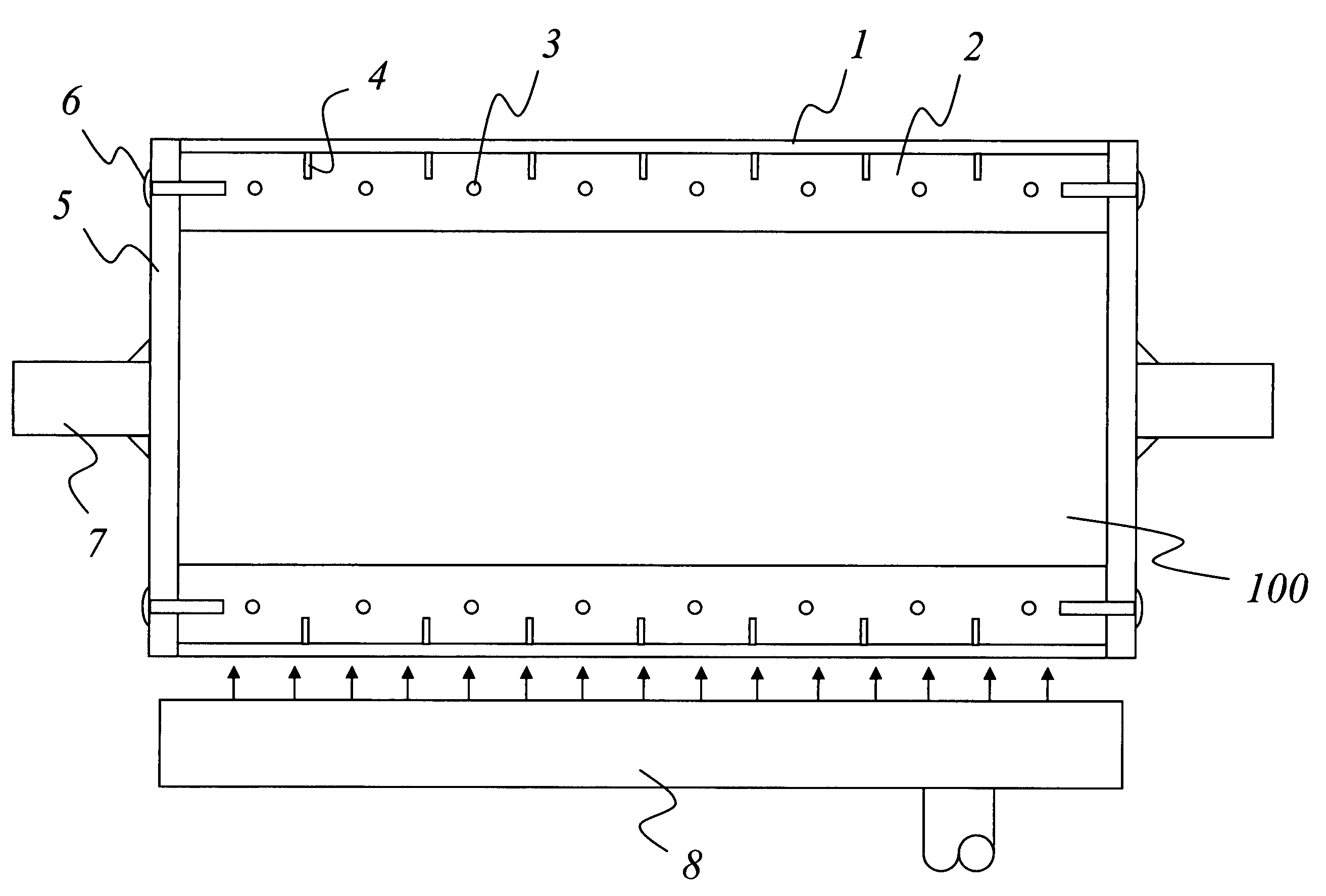
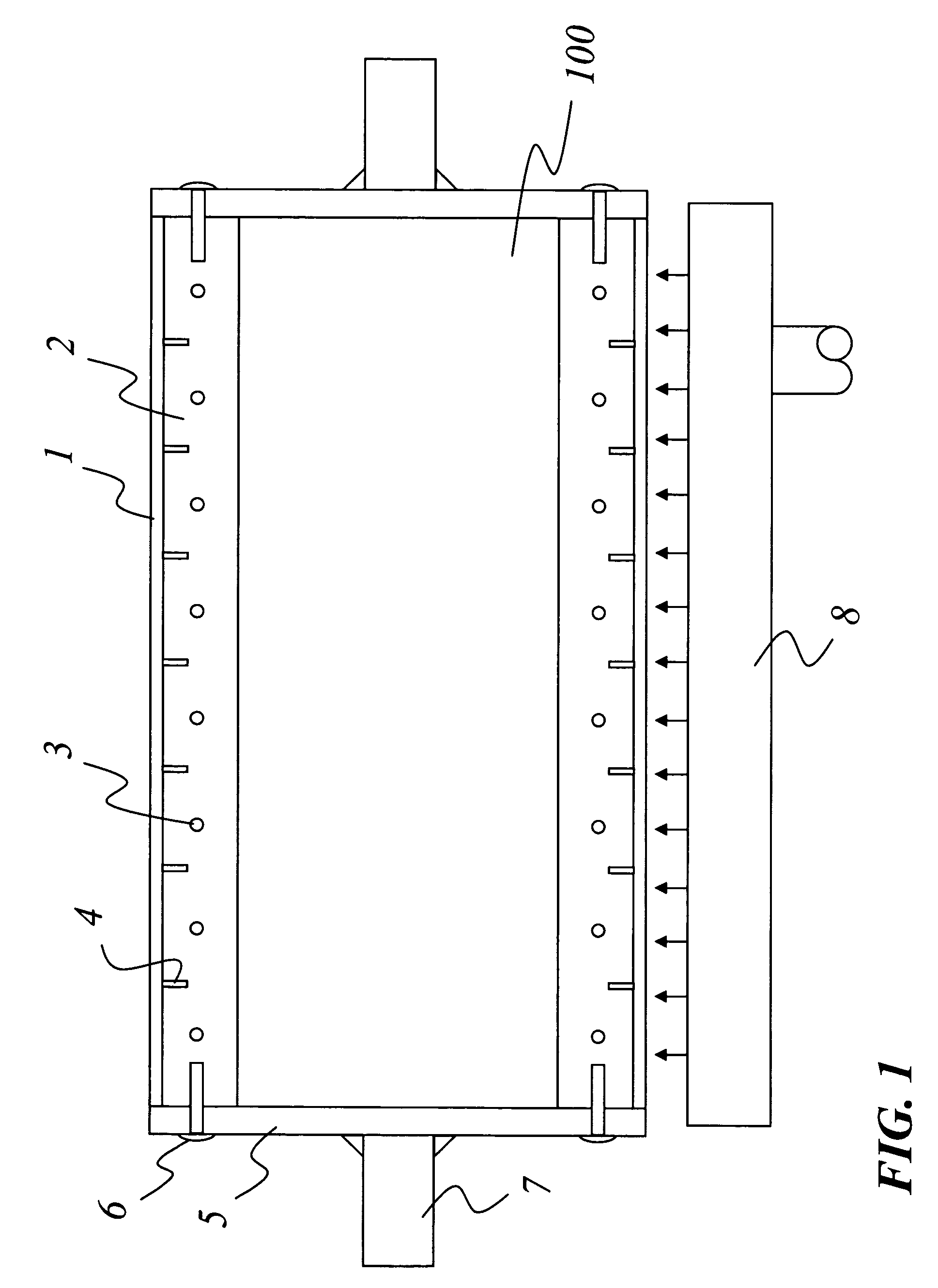
[0064] Referring to FIG. 1, a preferred embodiment of the rolls 100 of the present invention is shown. While there are numerous ways in which suitable composite rolls 100 can be constructed by those skilled in the art of manufacturing rolls to meet the needs of specific applications, the arrangement illustrated in FIG. 1 is just one example involving the present invention.

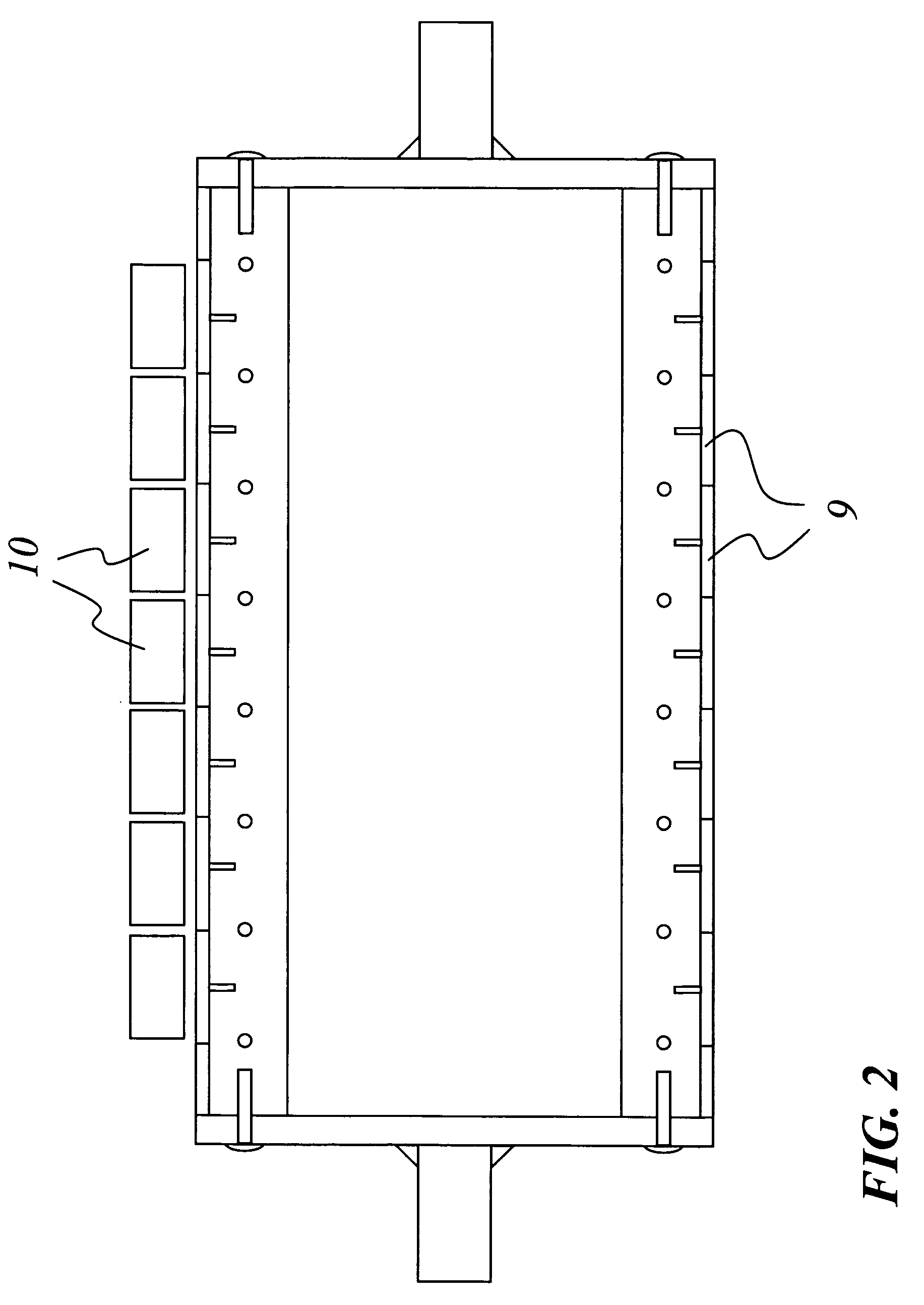
[0065] Referring again to FIG. 1 the composite roll consists of a thin ferrous outer shell 1 (approximately 3 / 16 inch thick) surrounding a thicker (approximately 4 inch thick) non-metallic sleeve 2 made from a preferably cast, suitable material, such as cement, that is adequately non-conductive in both electrical and thermal respects. The material making up the sleeve 2 should have a thermal mass that is one half or less than the thermal mass of steel. The cement (or equivalent) may have reinforcing bars 3 within it, and / or the outer shell 1 may have metallic protrusions 4 or hooks that will anchor it within the c...


PUM


Abstract

One embodiment of the heated roll apparatus uses an optimized roll whose surface layer is composed of a material responsive to being heated, particularly by external magnetic induction, and the depth of which, as well as the construction of the rest of the roll, uses one or more other materials whose properties are optimized with respect to maximizing the roll's rate of temperature change, minimizing energy usage, and performing the intended application. A thin outer ferrous layer over top of a thicker ceramic, insulating layer may be used. The roll may also include an outer layer that is responsive to heating, particularly by magnetic induction, and one or more inner layers of different material(s) chosen to increase the roll's rate of temperature change and reduce energy usage, but which are further selected to promote rapid lateral heat conduction to reduce lateral temperature variations. This roll could include a thin outer ferrous layer over top of a thicker aluminum core. The roll may instead be constructed of a single contiguous material (such as a carbon-fiber composite) that is particularly responsive to heating by magnetic induction, and which has a higher strength-to-weight ratio than ferrous alloys (i.e. cast iron or steel), thereby allowing it to be lower in weight and more thermally responsive than conventional heated rolls. The roll may also have a surface layer or contiguous depth composed of a material responsive to being heated, particularly by magnetic induction, but which in addition has a minimal outside diameter (regardless of its internal construction) in order to minimize its mass, so that it can be heated more quickly to a higher temperature, by a given heat input rate generated by any means, than would be possible with a larger, conventional heated roll.

Description

FIELD OF THE INVENTION [0001] This invention relates to heated rolls used in web processing operations such as: calendering; drying; laminating; embossing; pre-heating; corrugating; curing; heat-setting, shrinking; bonding; etc. It has particular application to roll surface materials responsive to high temperature induction heating, where energy losses associated with conventional, indirect heating systems can be significantly reduced. BACKGROUND OF THE INVENTION [0002] The surface layer of most heated rolls is typically thick-walled and made of a ferrous alloy, while other more specialized, usually unheated rolls use other metals (e.g. aluminum) as well as non-metal materials such as granite. Heated rolls are typically heated internally, using hot water, hot oil, or steam, and may also be heated externally using steam jets, gas flames, hot air impingement, infra-red radiation, or magnetic induction. The depth of the surface layer of conventional heated rolls is typically greater th...

Claims


Application Information

Patent Timeline
Patent Type & Authority Applications(United States)
IPC IPC(8): F28F5/02
CPCD21F5/021D21F5/024D21G1/028F28F5/02
Inventor LARIVE, RENE D.TAYLOR, BRUCE F.
Owner COMAINTEL
Learn More